Stepping back a bit. The excess loop gain in any circuit is what causes instability. Ultimately, the sure way to improve stability is to reduce the excess loop gain. This is always an option.
Interesting point. I wonder if increasing R12 to 470 to 560 would help. This would increase the negative feedback and reduce the closed loop gain to a more typical level. It looks like the closed loop gain is somewhere in the 30's right now. I think 470R to 560R would put it somewhere in the mid to high 20's.
Maybe this would help?
Maybe this would help?
I'm defining the excess loop gain as open loop gain minus closed loop gain. So it's better to increase the closed loop gain rather than reduce it. Better still to reduce the open loop gain. In general, the excess loop gain reduces the total distortion, but it's at the price of stability.
Stepping back a bit. The excess loop gain in any circuit is what causes instability. Ultimately, the sure way to improve stability is to reduce the excess loop gain. This is always an option.
Yes of course. I tried with by bypassing R11 with some other resistors (lowering the total resistance) which reduces the overall gain of the amp. The interesting thing is that, then the ringing at the positive side disappears. But only because the output level drops due to the decreased gain. Then the input is increased so the same output level again, the curve looks exactly the same again.
Also tried putting resistor across R11 in the NFB loop, but that only makes it worse. Adding I resistor in series the the cap works. But only by lowering the overall gain.
This is what I'm trying to make disappear;
So annoying, feels like it should within reach to get this working. Just getting rid of these ringing and it may perform pretty good actually. Adding more capacictance to the compensating cap C8 does the trick, but it's already at 100 pf.
I'm defining the excess loop gain as open loop gain minus closed loop gain. So it's better to increase the closed loop gain rather than reduce it. Better still to reduce the open loop gain. In general, the excess loop gain reduces the total distortion, but it's at the price of stability.
Sorry read your post first after posting my previous post. How do you mean? The closed loop gain is set by the NFB network I guess. But the open loop gain? What sets it?
Well after a lot of more trying and error I finally got rid of this oscillations, without increasing the compensating cap C8. Tried everything suggested by @WhiteDragon in previous post but nothing really had the effect I hoped for.
However It has to be something with the output/driver/VAS area my suspicions was. Also changing the bias current to the extreme took care of the ringing. So i put in a extra resistor (R16 in schematic) in the bias network. This didn't help until I put a cap in parallel with it. The value of the cap seems to be very picky, not to small, not too large. around 2n2 and the ringings no longer visible (with my crappy scope at least). I'm not sure why this actually help, so if anyone know, please tell.
Below is the square wave response of 20khz, into 4 ohm. Channel 2 is amp with TIP's for comparison. I agree it looks like it close to the limit of being overcompensated. Sine wave response look good know without any ringing.

However I think this is as far I'll get with this design (I also have to leave two weeks for work now). Maybe I just go back to the TIP's, I think actual listening and (maybe) distortion analyzing will decide. Thanks a lot for all of your help and input.
- C10 changed 10 100 and 10 n, did not have any effect, stuck with 10nF
- Changing R20 or jumping R19 had very little effect as well
- Degen still the same story, work but kills the slew rate.
However It has to be something with the output/driver/VAS area my suspicions was. Also changing the bias current to the extreme took care of the ringing. So i put in a extra resistor (R16 in schematic) in the bias network. This didn't help until I put a cap in parallel with it. The value of the cap seems to be very picky, not to small, not too large. around 2n2 and the ringings no longer visible (with my crappy scope at least). I'm not sure why this actually help, so if anyone know, please tell.
Below is the square wave response of 20khz, into 4 ohm. Channel 2 is amp with TIP's for comparison. I agree it looks like it close to the limit of being overcompensated. Sine wave response look good know without any ringing.
However I think this is as far I'll get with this design (I also have to leave two weeks for work now). Maybe I just go back to the TIP's, I think actual listening and (maybe) distortion analyzing will decide. Thanks a lot for all of your help and input.
Attachments
The resistor R16 is known as a current compensation resistor. It’s value is picky and 22R is in the right ballpark for a CFP OP. It offsets Re in the bias transistor Q9. It’s intended to make the bias voltage more stable.
Not sure why the cap helped. Make someone else has insights here.
Not sure why the cap helped. Make someone else has insights here.
You might want to check for stability with a reactive load before calling done:
https://www.waynekirkwood.com/images/pdf/Cyril_Bateman/Bateman_Speaker_Amp_Interaction.pdf
https://www.waynekirkwood.com/images/pdf/Cyril_Bateman/Bateman_Speaker_Amp_Interaction.pdf
"You might want to check for stability with a reactive load."

I predict this circuit won't survive the "capacitor test". It's already on the brink with a resistive load.
The thing here is that there are too many design mistakes and adding various bandages will be hit and miss and won't fix it properly. It needs a redesign. A good amp should be completely stable and silent.
I simulated this design and checked the loop gain. I'm not sure how to interpret this... The 180 degree point for checking margin is inverted. If I replace the IPS current source with separate generator, the phase margin looks like what I would normally see.
Is this normal for the as-built version with the IPS and VAS current sources tied together?
I attached my asc files if anyone is interested.
Original

With separated IPS current source

Is this normal for the as-built version with the IPS and VAS current sources tied together?
I attached my asc files if anyone is interested.
Original
With separated IPS current source
Attachments
Depends.
Phase of current sources remain in same phase if tied together.
usually with separate sources the input current source phase is much different.
but usually in the actual audio bandwidth.
I usually dont tie feedback sources together though. and dont use high Ft
transistors for feedback current sources. Because they can oscillate too
This case its likely with the higher Ft output transistors a cap over R11 could have worked.
at correct frequency would have changed margin phase as well.
could sim. as opposed to the TIPs which oscillated with feedback comp
Be interesting to sim anyways. 2n3906 might improve even more with less current
input stage could maybe go down to 1ma.
I wouldnt suggest for now. be easier in sim.
something I should have done anyways.
Degen value could drop as well with only 1ma.
Ive almost comically used 2N3906 because in sim
ive actually got rather good results with them.
the speed holds up at low current if they dont drive
difficult loads. so in this case the load is rather easy to drive
with enhancement
I predict this circuit won't survive the "capacitor test". It's already on the brink with a resistive load.
I agree it doesn't look very promising. Using the the faster output devices only ended up causing more problems than it solves I believes.
However the TIP version looked quite stable to me so then I return home I will probably do some more testing anyway. Please tell me about this "capacitor test". Got a link or so? Couldn't found anything by Google.
I usually dont tie feedback sources together though. and dont use high Ft
transistors for feedback current sources. Because they can oscillate too
Which transistors are you referring to the 2n3904/2n3906 or the 2sb669/2sd649? They both pretty high ft.
I was thinking of using 2sb669/2sd649 in the VAS, Q8 Q10 and Q11. But rejected that thought as totally unnecessary. No need spend hard to get 2sb669/2sd649, since 2n3906 totally can handle the voltage and current.
Capacitor test = put a capacitor across the speaker terminals, say 1nF, 10nF, 100nF, 1uF. See what happens to square wave. Keep amplitude low.
Be very careful because the amp may burst into oscillation without any signal and blow a gasket.
Capacitive loading adds phase shift to the open loop transfer function, reducing the phase margin. This is why some people add a series output inductor, which has opposite phase effect. But the combination of inductor and capacitive load will cause a resonance. Best to observe the output before the inductor.
Some people like me, guess that's what L1 is for. Never thought about connecting a capacitor as load during my previous test though. It will be very interesting to test then get possibility again, I suspect that the amp with the TIP's and the one with MJE150's may differ a lot. Thanks for the tip!
Capacitor test = put a capacitor across the speaker terminals, say 1nF, 10nF, 100nF, 1uF. See what happens to square wave. Keep amplitude low.
Be very careful because the amp may burst into oscillation without any signal and blow a gasket.
Capacitive loading adds phase shift to the open loop transfer function, reducing the phase margin. This is why some people add a series output inductor, which has opposite phase effect. But the combination of inductor and capacitive load will cause a resonance. Best to observe the output before the inductor.
Just to clarify, by "Best to observe the output before the inductor" I believe traderbam means take the feedback before the series inductor rather than after at the speaker terminal. Spot on!
Not just take the feedback before the inductor, but if you’re looking at it on the scope, look before the inductor. If you feed a PERFECT square wave into an L-C circuit you will see ringing across the C by itself. That ringing is normal and cannot be helped. As long as the ringing in the amplifier itself is minimal (like just a small overshoot and part of a single cycle) you’re ok.
Yes, attach the scope probe at the amp end of the inductor.
With some of my early designs (highly questionable in hindsight!), I would switch on and try a selection of caps. I held the cap in one hand and every so gingerly touched both leads across the speaker output...if the scope line blurred or disappeared entirely (!) it was time for a rethink.
With some of my early designs (highly questionable in hindsight!), I would switch on and try a selection of caps. I held the cap in one hand and every so gingerly touched both leads across the speaker output...if the scope line blurred or disappeared entirely (!) it was time for a rethink.
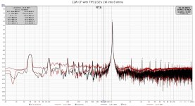
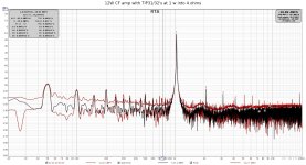
Finally got some time to finish this project. Had to abandon the MJE15030/31 design since I never got it stable enough. The TIP31/32 version seem to work ok and passed the "capacitor-test".
After building low distortion signal generator I could finally measure the distortion of the amp. The results are acceptable, but not great I would say;
0,0045 % THD (1khz) 1W into 8 ohms
0,0056% THD (1kz) 1W into 4 ohms
Fined tuned the bias current during the test for lowest distortion. It was pretty close to preset position of 8 mV across R33 + R34, but managed to decrase the distortion a few 0,001's at the end.
Attachments
- Home
- Amplifiers
- Solid State
- Complementary Feedback design amp oscillating problems