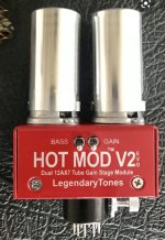
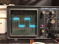
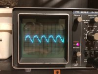
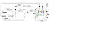
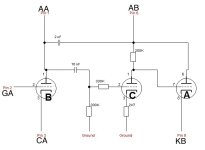
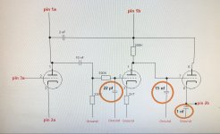
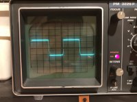
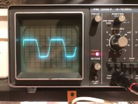
hello again .. I started this topic again because I have an oscilloscope. old for sure but it does its job very well .. so, I wanted to make an adapter called soldano hot mod. this adapter carries on it a valve tube called 6c10, very old with 3 triodes. so now how does this work,, i forgot to say that it is for a marshall jcm800 guitar amplifier. and we replaced the second valve tube of the amplifier with this adapter. what does it do? adds an extra amplification stage between the 2 triodes that the 12ax7 had .. and simply without pedals you have a natural pre amp stage with more gain (saturation) ...the problem is as follows, that the specific tube valve (6c10). it is quite expensive and very difficult to find, and that's why I decided to copy the design that is in the 6c10 but replace it with two 12ax7, i.e. the 3 triodes..in the end i made the design and tested it but it didn't work exactly as it should... now that i have an oscilloscope, i said to give it a chance to perfect it,,i simulated the marshall jcm800 preamp where the triodes were replaced with jfets j201 ... and it really works but sounds very similar .. when i also made the opator design and applied it to the simulation ... and i got exactly the same result as with the normal amplifier,and now the oscilloscope takes place, I should emphasize that the normal signal without the adapter is asymmetric and clipped .. after I applied the adapter the signal comes out as a clean square. and the amp sounds a lot of noise and buzz.. so I thought of a trick to approach the sine signal. I put in the output a 10K resistor in series and a 10n capacitor to the ground, and again a 10K resistor in series and a 10n capacitor to the ground and the same thing again... and somehow it made the signal better,there was a reduction in volume but it worked. more saturation and gain,,,I would just like to ask, how can the sign not come out? I send photos of designs and the oscilloscope. if anyone has any advice or help to "tame" the signal , I would appreciate it
Attachments
Hi plig88, this is the wrong section of the forum. It should be moved to instrument amplification.
Basedon my experience 22 pF is too low and 2.2 nF and especially 15 nF are too high.
Usually very high values at the end means you have too many weird harmonics that you need to cut before.
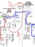
On top of that, for a Marshallesque sound I'd go for a cold stage (snubbered by 470p to ground, not to B+, to avoid to inject ripple into the signal) at the beginning, RC coupled without voltage dividers to a warm stage then DC coupled to the cathode follower.
Basedon my experience 22 pF is too low and 2.2 nF and especially 15 nF are too high.
Usually very high values at the end means you have too many weird harmonics that you need to cut before.
On top of that, for a Marshallesque sound I'd go for a cold stage (snubbered by 470p to ground, not to B+, to avoid to inject ripple into the signal) at the beginning, RC coupled without voltage dividers to a warm stage then DC coupled to the cathode follower.

By the way I cant understand how to change the positive Waveform , the only that change it is the negative … must start learn more things for signals
I thought of something else that I didn't notice at first, my amplifier (style jcm800) at its output gives a signal which is quite curved in the positive part and clipping in the negative part,,, which has absolutely no relation to the emulation I made with the j201,, because in what I made it gives me the same clipping both in the negative part and in the positive part…. so I better do my tests on the real amplifier with the tubes, to get a specific result, because probably the jfets makes the clipping on the both sides, I guess
the truth is that this is how I do the test. 🙂 I mention it at the beginning of the post, that I made an emulation of preapm (jcm800)... I know it's stupid of me to test it like this, but I thought it would be easier than opening the normal amplifier and doing the tests there. but it is also strange that although the signal shape is different, the sound of the j201 with 12ax7 is very close.
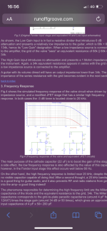
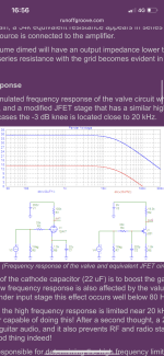
I check this site who talk and compare valves tubes with jfets https://www.runoffgroove.com/fetzervalve.html#12
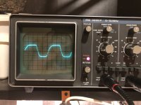
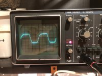
And I remove the bypass cap from 1 stage cathode and the signal change , now is curved from the negative side and clipped from the positive ( on the Marshall it’s upside down ). I started learning more things now that I got an oscilloscope.
And I remove the bypass cap from 1 stage cathode and the signal change , now is curved from the negative side and clipped from the positive ( on the Marshall it’s upside down ). I started learning more things now that I got an oscilloscope.
Attachments
This is truth …. Fffff I’m so confused , I don't know where to start… by the way thank you for your help , best regardsOnce you heavily clip, they might seem to sound vaguely similar. Before that, nah!
Soooo new update ,, I opened my (style ) jcm800 and I starting some tests ,, I put the probe after the tonestack , basically on master volume .. everything on the signal looks fine . Now I start to make the adapter . Better results for oscilloscope have with probe after tonestack or before ?
There's no better, you are looking at different things.
I'd just listen to the sound I get, without worrying too much on the simmetry of the signal: it will never be at mid-high gain, because both the cold stage clips asymmetrically, and the cathode follower does as well.
I'd just listen to the sound I get, without worrying too much on the simmetry of the signal: it will never be at mid-high gain, because both the cold stage clips asymmetrically, and the cathode follower does as well.
for sure the sound is the last result ..better for me as I think of it to enter the probe before the tonestack. whenever now I will start improving the adapter. so as not to make value linear . If you want, see this link And you will understand exactly what the adapter does
by the way it’s very clever way to add extra gain stage with out open the amp … this is I think , and anytime pull it off and the amp return to factory settings 🙂
Good morning from sunshine Athens of Greece . for so long, I was stuck with the original design of the adapter with valve 6c10,,, and I was trying to copy this design, I think that was my mistake, I didn't focus on the fact that I should just add 1 gain stage in between ... so I watched the design of the slo100 and I will copy the gain stage that is before the cathode follower .. I think it is a start . what do you think ;
Attachments
- Home
- Live Sound
- Instruments and Amps
- Soldano hot mod v2 on oscilloscope