ncrease C3 from 68 pF to 560 pF and R1 from 150 ohms to 1K ohms. Else your AMP works like the super wide frequency radio receiver.
Sure, this would change the cut off frequency of the low pass filter from 15Mhz to about 200khz. Sure it couldn't hurt I guess, but most designs I've seen dos not even has a lowpass filter at the input. Don't know why Slone put it here, but kept it like it is.
To really stop RF you need that input capacitor direct across the input jack where it stops RF currents from entering the box at all.
R5, R6 is degen or degeneration. And without going into a long textbook explanation. Is very important key to getting a amplifier unconditionally stable.Yes, this is what did the trick I think. After changing R5 R6 to 330, I could remove the caps across B C at Q14, Q15. But please explain how this works,
A bigger cap (68pF or so) did not have any effect though. Found this a little strange, but maybe the 10 pF cap worked like a antenna or something maybe.
fT = gain bandwidth of the output transistors?
Often missed of misunderstood by many. But once used, it fixes common behavior of a basic differential amplifier. simplified, it flattens the overall curve or effect of transistor behavior or GM doubling. Which very much becomes a issue at high frequency, and generalized basically a majority of stability and overall phase margin of a feedback loop, most issues will be high frequency.
Cdom or miller compensation C8 is important as well, but often the value just gets increased and increased trying to address a issue.
The correct value is needed. But if to high, it will effect slew rate of on or off time of the output devices. Which can cause more damage than
good. Again leads back to degen which actually fixes the issue. Then people get amazed how low value Cdom can actually be. Still needed
but the usual approach of increasing and increasing to stabilize a amplifier. Anyways as you noticed removing caps across Q14, Q15
they are no longer needed. Excellent and as expected, not needed and just a common approach to toss caps at everything trying to address
a stability problem which is actually fixed by degen. Otherwise again the common approach to slow the slew of the drivers with caps. not good
it will slow on or off slew rate, or turn off turn on times. and actually can create more problems.
In reality as noticed once DC offset was corrected the amplifier only rings on the negative rail, and that is common behavior for CFP.
seeing ringing on positive rail instantly tells me DC offset issue. Any ways point is. If drivers are compensated only Q15 would need a cap.
The approach has been done many times. logical assumption since the negative rail rings, so compensate. Again not needed. Degen eliminates
the issue. and again slew rate is negatively effected. not needed.
Far as finally fixing the common negative rail ring. to not have a negative effect on slew rate like most do with Q15 compensation.
A decent phase margin is achieved by compensation over the feedback loop. Hence the cap over R11. yes correct a value too low
will cause ringing. Gain or Q from the filter at wrong frequency is being added. so phase margin is wrong. Ring.
If correct value based upon the value of R11 is used. Then the on time of Q14 and associated power transistors its driving is finally
corrected. And again the slew rate or on time of Q15 is not negatively effected like most do with cap compensation.
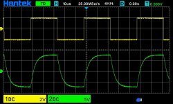
You noticed no difference with sine wave analysis. which is good, you shouldn't. Using square wave at high frequency at 20 to 22 kHz
you would then see, the effect of the slew rate I was talking about. Mainly on time of the negative rail causing all the problems. Ironically
the real problem is the off time of the positive rail. And that is observed with any complementary BJT pair. So it kinda funny. CFP will ring
on the negative rail. So people instantly start throwing caps at the negative rail. Real issue is off time of positive rail and cross conduction
that CFP will have at high frequency. So sum it up. Positive rail turns off slower, cross conduction causes...negative rail to ring.
anyways yada yada. Basically the negative rail wont ring, and slew rate wont get murdered with feedback compensation over R11.
And yes with sinewave at low frequency you wont see change. With actually square wave to observe on , off time it will be seen.
And actually if you dont see much and think im crazy...even better because again the real magic is the degen and even proves more how effective
it is.
Good idea to test the slew rate, don't know why I haven't thought of it yet. So I did, hooked it up with a 20khz square wave and connected a 4 ohm load to it. As you can see it is pretty poor... around 2,5 V/µS or so. Tried some different values of cap across R11 and 68 pF is most I would use. 100 pF and up greatly reduces the slew rate.
Maybe it's another VAS i need instead? 2-pole compensation maybe.
Attachments

What is your value for miller comp or C8
I believe you said that was way up at 150p.
Which will reduce slew.
degen will reduce its value considerable.
you could go back to 68 p even try min 56p.
Otherwise if 18 kHz or up looks very triangle its either
filtering or compensation. Or driver current either to high
or too low.
Degen will allow the lowest possible compensation values.
If high frequency is still triangle then your hitting the device limits.
Or as mentioned with slower devices, with low gain.
They load down the drivers.
Leads back to the question I didnt answer
and seeing it on the scope can make sense.
Tip31/32 gain drops under load and at high frequency.
And overall not much faster than .5 to 1 mHz
Where most common power transistors for HiFi
be the usual 30 mHz. and under load at HF will drop
to 18 to 22 mHz
Otherwise leading edges you show are rather smooth
no ringing. So it is rather stable.
Last edited:
It has been recommended in this thread.
I should absolute change the values:
R1 = 1k
C3 = 470pF
This will stop oscillations, I think.
The amplifier will still be fast internally.
And I would use the 100pF at Q14 Q15.
I should absolute change the values:
R1 = 1k
C3 = 470pF
This will stop oscillations, I think.
The amplifier will still be fast internally.
And I would use the 100pF at Q14 Q15.

Overall in all simplicity. Miller compensation
is the most defining pole for amplifier stabilization.
And actual bandwidth of a amplifier depending how stubborn
it is with stability will be about 200 KHz at the lowest to around
250 to 330 KHz if your lucky. 250 / 280 about normal
So C8 and degen is most the phase margin.
Far as not destroying slew rate. by typical methods.
Like driver compensation or base resistors.
Extra pole over the feedback loop works best for CFP.
So 12k feedback resistor. 68p puts you at one extreme
195 KHz for a stubborn amp 33p puts you at the other extreme
402 KHz. and 250 to 280 lies between those standard values.
As you found out going to low can cause ringing.
If degen is enough to have very rounded slopes.
then compensation over feedback just removed.
With this kind of bias tracking I would strongly recommend minimum 220 nF from base Q14 to base Q15.
Also, base stoppers Q16-19, 10R or more, would be advisable 🙂
Also, base stoppers Q16-19, 10R or more, would be advisable 🙂
R1 and C3 is not to stabilize, it is a radio frequency filterIt has been recommended in this thread.
I should absolute change the values:
R1 = 1k
C3 = 470pF
This will stop oscillations, I think.
The amplifier will still be fast internally.
And I would use the 100pF at Q14 Q15.
for the input.
The amplifier is stabilized with miller comp C8
and differential degeneration.
His amplifier is now stable now because originally.
we had positive DC offset because the current sources needed
adjustment. After DC was corrected. Degen increased so
miller comp can be low as possible. and we dont ruin on off times.
with the usual transistor nonsense of base resistors or driver compensation.
Nonesense because of cross conduction that CFP has and will never go
away. In fact as mentioned adding base resistors with Darlington's not so bad
CFP you just causing more cross conduction by adding base and driver caps.
Adding degen removed the classic stability issue
of CFP. Any typical BJT actually only needs around 22p for C8
for Miller compensation especially with beta enhancement.
But we all know the phase margin usually
wont let that happen because of feedback. Hence 47p to 100p more common.
and 100p would be a complete joke with Q10 beta enhancement. Since that is
a majority of the point to use it. Reduce miller comp and differential load.
Far as the mystery of R1 and C3. Radio interference reduction.
Lowest AM band approaches 3 MHz
So 1k would only need 53p for 3 MHz
people wanna make parts count high. C8 is basically
gonna be 68p anyways. You just toss a 1k resistor at the input.
and use the same value 68p. And your all done. No radio at the input.
In fact it is not that hard to remove RF from input. Even with no resistor.
and 100p. Radio usually goes by by. So even the current 150 ohms and
68p will be fine.
If you want exact value 150 ohms would need 353p for 3MHz
and 330p or 470p standard values be more than fine.
Hardly doubt radio is getting in so the current values more than fine
again no, base stoppers and driver capacitor compensationWith this kind of bias tracking I would strongly recommend minimum 220 nF from base Q14 to base Q15.
Also, base stoppers Q16-19, 10R or more, would be advisable 🙂
will increase instability with CFP and cause more cross conduction.
The amp is stabilized like any other amp. C8 miller comp
And differential degeneration.
Once you add degen. no base or driver caps needed.
Same with Darlington amp.
Stability issue with differential amp is mainly from feedback.
The problem is fixed with the actual problem. Feedback
right into the differential. Degen.
If you added base resistors to power resistor to stabilize.
That is another issue. mainly with Darlington's.
Current surges from load, or driver without enough DC current
will ring. That problem is fixed with the power rail. you need more
power supply decoupling. And with any amplifier output transistors
need decoupling capacitors mounted as close to the transistors as possible.
that is board design.
The same current surges can also destabilize the VBE multiplier.
So common to add C10. which is 1 to 10uf to stabilize the voltage.
And then a additional smaller cap 10n to 100n for high frequency surges.
Same with power rail. you want large caps for low frequency
small caps for high frequency. typical design is 470uf and 100n
mounted on the board as close as possibly to power transistors.
CFP output stages are trickier than EF ones to make stable though - this is nothing to do with global feedback compensation, more to do with the local CFP feedback and accidental creation of parasitic Colpitts/Hartley/whatever RF oscillators. Adding some resistance/ferrite beads to transistor bases to damp any parasitic LC parasitics is one way that can help, or adding various Zobel networks (again to add damping). Rock-solid rail decoupling at RF can definitely help, but you have to analyze your grounding from an RF perspective, not a star-grounding audio perspective - layout and stray inductance are important at these frequencies.
Aside:
Just quickly converted my little complementary power follower to a CFP, Sziklai. Not the first time. Minimal increase in order, but also in artificiality, doughiness, dullness. Once again, a "technical" veil is drawn into the sound. Naturalness and liveliness are lost.
I also recommend to build up the Sziklai from the respective complementary pairs ("crossing out" of the different tonal characters of complementary transistor pairs), to make the base resistors adjustable and to adjust them for optimal sound. The Millers as small as possible, so that the amplifier runs stable. Nothing more.
"Build back better" now;-)
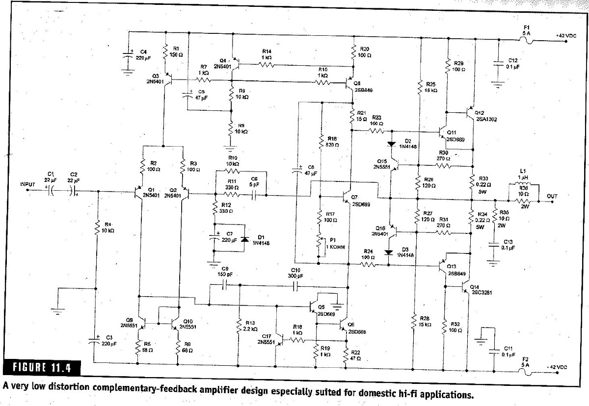
The design is from Randy Slone*s "The Audiophile's Project Source Book" so I doubt it's a design fault.
Did Slone's schematic look like this: https://www.diyaudio.com/community/threads/randy-slone-6-6-design.50259/post-2644785
It differs a bit from yours attached in post #1.
ok here's the schematic mentioned in my previous post (I just learned to link to a picture already posted here on DiyA
:) ).Today I've done a lot experimenting and so far I changed;
- R5 and R6 to 120 ohm.
- Compensating capacitor C8 to 100 pF
- Zobel network resistors R38 (and R37 at the same time) to 2 W (got a little hot then running a square wave constantly)


Don't know why the input signal (channel 1) "bounces" like it does though.

Output power ok, approx 18,9 W RMS into 4 ohm load.
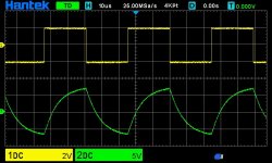
Also tried a lot of other configurations such as two pole compensation, but never got it working any better. Putting a capacitor across R11 still seems to be a bad idea, anything below 22 pF or above 68 pF actually introduced some HF ringing at negative side of the signal.

- R5 and R6 to 120 ohm.
- Compensating capacitor C8 to 100 pF
- Zobel network resistors R38 (and R37 at the same time) to 2 W (got a little hot then running a square wave constantly)
Yes, my tests today tells the same. However going under 82 pf for C8 made the amp to ustable, so choose 100 pF isntead. To increased the the slew rate I tested to change the degen resistors, which had the most effect of the slew rate. Actually tried 65 ohms to (original design 100 ohms) and it worked ok. But the amp was a little bit unstable, touching the heat sink with your hand and no input put it into oscillations. 100 ohms for degen resistors actually worked this time with 100 pf for C8, don't know why it didn't yesterday. But I choose 120 ohm for extra stability (and a little reduced slew rate, which now is about 15 V/µs which is totally acceptable.What is your value for miller comp or C8
I believe you said that was way up at 150p.
Which will reduce slew.
degen will reduce its value considerable.
you could go back to 68 p even try min 56p.
Don't know why the input signal (channel 1) "bounces" like it does though.
Output power ok, approx 18,9 W RMS into 4 ohm load.
Also tried a lot of other configurations such as two pole compensation, but never got it working any better. Putting a capacitor across R11 still seems to be a bad idea, anything below 22 pF or above 68 pF actually introduced some HF ringing at negative side of the signal.
Attachments
Did Slone's schematic look like this: https://www.diyaudio.com/community/threads/randy-slone-6-6-design.50259/post-2644785
It differs a bit from yours attached in post #1.
No, that one you linked I belive is from his book "High Power Amplifier Construction Manual". The one I'm trying to build is fig 6.10 (High-perfomance 12 W rms amplifier) from his book "The Audiophile's project sourcebook".
They are quite similar though, and one of the reasons I tried to construct this one is because it's almost identical to fig 6.11 from the same book. Fig 6.11 is a lot bigger amp 120W and uses MJ15004/MJ15003 as output devices. So I though I could get start messing around with this much cheaper one first...
Also tried a lot of other configurations such as two pole compensation, but never got it working any better. Putting a capacitor across R11 still seems to be a bad idea, anything below 22 pF or above 68 pF actually introduced some HF ringing at negative side of the signal.
Nevermind this last pic, it was without any load. So thats why the slew rates looks to be around 30V/µs or so. It was with 65 ohm for degen resistors R5 and R6 and 100 pf for C8, then I tested with some capacitance across feedback resistor R11, but I never got anything useful out of it. Only more ringing as you see.
The best working amp so far (I think) is that I've posted in the last schematic.
- Home
- Amplifiers
- Solid State
- Complementary Feedback design amp oscillating problems