In the
Testing the pcm1794 thread,
https://www.diyaudio.com/community/threads/testing-the-pcm1794.221743/
smms73 described an I/V test rig comprised of:
What I need is fast solution to getting acceptable sound from the output of a PCM1794. Something one just plugs RCAs into and get okay sound (or at least a hint of what is possible with the PCM1794)
Will the test rig described above suffice?
Or does one need more stuff added?
Testing the pcm1794 thread,
https://www.diyaudio.com/community/threads/testing-the-pcm1794.221743/
smms73 described an I/V test rig comprised of:
https://www.diyaudio.com/community/attachments/opamp-iv-png.306974/this test was made by connecting the pin IoutL+ to a classical ampop I/V converter (opa2134) with a resistor of 50 , 100, and 150 ohms in series.
the pin IoutL- was connected to ground.
What I need is fast solution to getting acceptable sound from the output of a PCM1794. Something one just plugs RCAs into and get okay sound (or at least a hint of what is possible with the PCM1794)
Will the test rig described above suffice?
Or does one need more stuff added?
I would just follow the data sheet and figure 24, pretty simple.
I/V Section: The current of the PCM1794 on each of the output pins (IOUTL+, IOUTL–, IOUTR+, IOUTR–)
is 7.8 mA p-p at 0 dB (full scale).
The voltage output level of the I/V converter (Vi) is given by following equation:
Vi = 7.8 mA p–p × Rf (where Rf = feedback resistance of I/V converter)
An NE5534 operational amplifier is recommended for the I/V circuit to obtain the specified performance.
Dynamic performance such as the gain bandwidth,:
Attachments

Yeah I saw that ... "simple," really ? ... with all that stuff going on?I would just follow the data sheet and figure 24, pretty simple.
Just need something to get feet wet. If I like it, I may even be enticed to pursue further.
It really is pretty simple, don't let it scare you. Can you work with the surface mount PCM-1794?
Do you just want to breadboard this for a quick try out, or keep it for a longer time?
Remember you do need the output filter (in the second op amp stage) to get rid of the digital "noise".
Here are cheap, completely built-up boards you can easily try out, no idea how good they are. There are others, too.
https://www.aliexpress.us/item/3256804416281126.html
https://www.aliexpress.us/item/3256804416615342.html
Last edited:
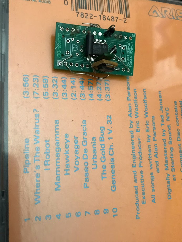
The photo shows as far as I got 12 years ago.It really is pretty simple, don't let it scare you. Can you work with the surface mount PCM-1794?
Do you just want to breadboard this for a quick try out, or keep it for a longer time?
Remember you do need the output filter (in the second op amp stage) to get rid of the digital "noise".
I saw Fig. 24, and thought ... "way too much work".
Maybe "Hawkeye". So, no "Voyager" and the La Grada Famila is still un-completed to date.
How about the smms73 circuit in the top post? If the simple smms73 circuit works, even a little, I may even (ultimately) tube it.
Simplest and cheap - will be 4 resistors for I/V (2 for each stereo channel) and dual OP (one OP per channel) like NJM358 as diff. amplifier.
How about some values?Simplest and cheap - will be 4 resistors for I/V (2 for each stereo channel) and dual OP (one OP per channel) like NJM358 as diff. amplifier.
Maybe draw up a drop-in circuit on the back of envelope . Take a pic. Post.
grunf's PDF?his is not "Simple & cheap" 😏
But neither is what you responded with:
http://www.pavouk.org/hw/modulardac/en_pcm1794a.html
Draw up your:
It's "simple and cheap" to Google web pages -- low hanging fruit. However: If one puts forth the effort, the Cosmos allows for ... (not a fruit -- it's healthier)Simplest and cheap - will be 4 resistors for I/V (2 for each stereo channel) and dual OP (one OP per channel) like NJM358 as diff. amplifier.
If you are able to read schematics, You can see there exactly what i said - I/V on resistors (R17, R18), and diff.amp on one OP.

Use four 120 ohm resistors for I/V and four 1uf capacitors in series to output. No filters is no problem for just get proof of concept.
But there are 22 parts total here. What you post is not much different to others' high-part-count suggestions. If it takes that many IV parts for the 179x to work okay , then I may abandon the project for opt for he $12 dual Chinese kit,If you are able to read schematics, You can see there exactly what i said - I/V on resistors (R17, R18), and diff.amp on one OP.
BTW: Who is pavouk.org ?
No clue here ... someone please sketch this out. ... smms73 stated something similar in the pcm 1794 thread ... and it turns out there was an op-amp that popped up in a later photo.Use four 120 ohm resistors for I/V and four 1uf capacitors in series to output. No filters is no problem for just get proof of concept.
I can attach to the small proto in my earlier photo.
If I get some clue as to what to expect, I may even be persuaded to along this ...
https://6moons.com/audioreviews/yamamoto7/dac.html
Yes, but simple and cheap.But there are 22 parts total here.
BTW, using dual OP - not 22, just 19: 14 resistors, 4 capacitors and one chip.
opt for he $12 dual Chinese kit,
LM358 or 2904 (which is the same), costs 15-20 cents.
But i
f you have a sensitive amplifier, you my use only resistor-based I/V with one of the DAC's differential output.
You will need only one resistor for I/V and one DC-block capacitor. Nice to have also RC-filter at the outputs,so
totally - 2 resistors+2 capacitors.
This maybe even better than TDA1540 or 1543, or similar garbage.
Who is pavouk.org ?
I don't know, I was too lazy to draw a schematic, so I just found a similar one on the Internet
The OP asks a question, links to a page or two and the answer is invariably to be found, in plain sight, in one of those links.
Be brave -- someone.I don't know, I was too lazy to draw a schematic
Fill in the blank.
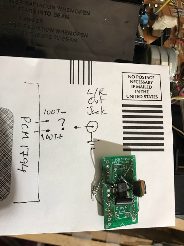
As few parts as possible in "?" to make the 1794's output an acceptable signal and free of DC offset.
You/someone must draw it. Draw it Yourself. DIY.
- Home
- Source & Line
- Digital Line Level
- PCM1794 -- simplest I/V possible needed