
Hi Mark,
you are right. I should have taken that into account before modding the layout and sending the files to JLC
I have bought two OPAs from a german eBay Shop... but I'm pretty sure that they are fake.
🙄
you are right. I should have taken that into account before modding the layout and sending the files to JLC
I have bought two OPAs from a german eBay Shop... but I'm pretty sure that they are fake.
🙄
Last edited:
2SD2081 I get from Bdent per Jeff's recommendation, otherwise I think 2SD2014/2SB1257 should be fine.I've made a little progress with the great "template" from Jeff. 🙂
Unfortunately there are some problems to get "real" 2SD2081 and OPA604 (ATM) 🙁
Would there be adequate substitutes for them? 🙁
BR Falk
OPA604 partsconnexion has them, also Cimarron technology has them in soic-8 plus adapters, otherwise i'd probably do another stage to drop the rail for the opamp supply to run other types.
Falkomat, by coincidence I found new/unused original OPA604 (and OPA603) in an ESD safe container. If you need them please send me a PM.
Last edited:
I am using it as my main preamp since more than 6 months now.

Thank you, gentlemen,
I'm sure this will be a new build candidate in 2024 as well as a great companion to the Q17 amplifier I'd like to complete this year.
I will definitely build it on Jeff's board, also thanks to Jeff for sharing his project 🙂
I'm sure this will be a new build candidate in 2024 as well as a great companion to the Q17 amplifier I'd like to complete this year.
I will definitely build it on Jeff's board, also thanks to Jeff for sharing his project 🙂
Hello everyone,
After building the WHAMMY, "NOIR," and an F6, I would like to create the HPA-1 Jeff version.
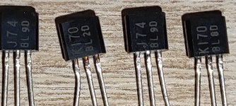
It will be equipped with 2SK170/2SJ74 for the JFETs, KSA992/KSC1845 for the BJTs, and FQP3N30/FQP3P20 for the MOSFET
I have taken the latest schematic (as far as I know), kept the main architecture, and made changes only to the power supply by switching to a CRCRC configuration. The 5V will be separated, and the relay control (power/inputs/outputs) will be managed by an ARDUINO.
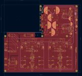
I have revised the PCB layout and added a few test points. Do you have any comments or improvements to suggest?
Regarding the 5V circuit, I am replacing the BA7812 with a BA7805. Should I modify its surroundings?
Have a nice day, Jérôme
After building the WHAMMY, "NOIR," and an F6, I would like to create the HPA-1 Jeff version.
It will be equipped with 2SK170/2SJ74 for the JFETs, KSA992/KSC1845 for the BJTs, and FQP3N30/FQP3P20 for the MOSFET
I have taken the latest schematic (as far as I know), kept the main architecture, and made changes only to the power supply by switching to a CRCRC configuration. The 5V will be separated, and the relay control (power/inputs/outputs) will be managed by an ARDUINO.
I have revised the PCB layout and added a few test points. Do you have any comments or improvements to suggest?
Regarding the 5V circuit, I am replacing the BA7812 with a BA7805. Should I modify its surroundings?
Have a nice day, Jérôme
Attachments
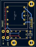
You might want more clearance on the 230V lines. While IPC2221 says 0.4mm is enough with a conformal coating, there's no solder mask on the IN/OUT pads, so I'd want more around those. I usually just use 2mm since my designs aren't that dense and I can afford the space.
You may need a bit bigger transformer with the CRCRC PSU, depending on what values you're using for C and R.
You may need a bit bigger transformer with the CRCRC PSU, depending on what values you're using for C and R.
Thank you for the feedback, Jeff.
I will correct the traces and the IN/OUT pads.
Regarding the filter, I will keep the 40,000uF by using 3x6800uF capacitors. I don't want to affect the bass frequencies. As for the resistors, I will calculate them using the formula 1/CW with a cutoff at 50Hz, which gives me a value of 0.47 ohms.
Unless I'm mistaken, currently with 2.2 ohms, the cutoff frequency is around 7Hz. Is it necessary to go that low?
The transformer will be a Toroidy 120VA 2x24V.
Have a nice day, Jérôme
The first set of capacitors need to have enough ripple current capacity. The 10,000uF ones I used (Nichicon LLS 50V) have about 5A, which give a large safety margin. You probably don't need that much, but don't go too low.
The resistance is not so much about the cutoff frequency. It's really a trade-off between how much voltage you lose, how much heat you generate, and how much you pound that 50Hz ripple flat. The series regulator after the CRC doesn't need a lot of headroom, but it still needs some. (I used a 25V transformer to give me a bit more headroom with the 2R2 I used.)
I'd suggest playing with the values in PSUD2.
I wasn't familiar with PSUD2, but it's really useful.
I simulated my power supply with a 40 ohms load for a current of 600mA.
I obtained a current of 2A in the first capacitor section, and my UKTs can handle up to 2.5A.
My output voltage is 24.5V, A bit tight?
I simulated my power supply with a 40 ohms load for a current of 600mA.
I obtained a current of 2A in the first capacitor section, and my UKTs can handle up to 2.5A.
My output voltage is 24.5V, A bit tight?
Attachments
- Home
- Amplifiers
- Pass Labs
- Pass HPA-1, what do we know?