OK, you've outlined three points which may be confusing me.You are being confused by multiple points.
First, the plot I provided was NOT a plot of rolloff with frequency, but a plot of the -3dB point as a function of volume control shaft position.
Second, you cannot just ignore impedances in the signal path when analyzing a circuit. The output impedance of the cathode follower is in series with the capacitor as is the upper portion of the volume control. You have to account for ALL of those impedances when calculating the frequency dependent rolloff.
Third, the transfer function (i.e. output/input rolloff) as a function of frequency is dependent on the voltage control setting. The series capacitor does still function as a low frequency pole forming a "high pass" filter, but the circuit is more complicated than just a capacitor and a resistor to ground. And the volume control is non-linear. (see attached plot)
The -3dB point is dependent on ALL the impedances in the path. In this case the resistances in series with the capacitor (i.e. the CF output impedance AND the portion of the volume control above the control wiper), the portion of the control below the wiper tied to ground, and the input impedance of the downstream amplifier which is in parallel with the lower portion of the volume control. When calculating a voltage at a node in the circuit, you must account for ALL impedances between the voltage source and the node and those between the node and ground.
I don't believe I'm confused about the first one . . . I understand that it's not plotting rolloff with frequency. What it's saying is that the -3db point for a 10k pot (orange line) starts at 15Hz and is unchanged until the pot is at 70% rotation, at which point the -3db point rises to roughly 28Hz at full rotation.
I understand the chart. What I don't understand is the results.
Rather than look at how it changes through the rotation, lets just look at three different data points using the chart of the audio taper pot's response that you just posted (not the chart discussed above) - 30%, 50%, and 100%. At 30% the resistance to ground is roughly 400 ohms, at 50% it's 1k and at 100% it's 10k.
Each of these is in parallel with the 10k input impedance of the amp. The resulting R values are: 385 ohms at 30%, 909 ohms at 50% and 5k at 100%.
For the moment we'll ignore the other factors (impedance of CF and series R of the pot). If no other factors were involved, the high pass rolloff points when used with a 1uf cap are: 413Hz at 30%, 175Hz at 50% and 32Hz at 100%.


As for the second point . . . I understand that there are other factors that need to be considered. The factors you mention are the output impedance of the CF (612 ohms) and the top portion of the pot that's in series with the signal. Those resistances are 9.6k at 30%, 9k at 50% and 0 at 100% pot rotation. What I don't understand is how to factor them in.
As for the third point . . . at the end you say "When calculating a voltage at a node in the circuit, you must account for ALL impedances between the voltage source and the node and those between the node and ground."
When you talk about voltage, I assume that you're talking about the signal level being sent to the amp and your concern seems to be tracking the level of voltage at various points (nodes) along the way.
But my concern is not about voltage, it's about the -3db rolloff point with the volume control at various settings, particularly ones that are likely to actually be used - such as 30% and 50%.
Your chart indicates that the -3db point at both 30% and 50% is 15Hz and at 100% it's 28Hz. If other factors were not involved, the frequency would vary as the pot is turned up and at 100% it would be the lowest, not the highest.
So your chart indicates that the influence of the impedance of the CF and the series R of the pot changes the rolloff at 30% from 413Hz to 15Hz, at 50% from 175Hz to 15Hz and at 100% from 32Hz to 28Hz.
You've posted the results in chart form but not the actual calculation. What formula is used to integrate effect of the CF impedance and the series R of the pot with the data points (the 1uf cap and the various R to ground values) used by the high pass calculator? If you could "show your work" rather than just the answers it would help.
Oh, and . . . While I appreciate you posting the link to the Wikipedia article on "Two Port Networks", that's the type of article that might make sense to an engineer or someone with higher math skills but it's gobbledygook to a layman like myself. I suspect that even many of the more technically minded members here might struggle with it too. So thanks, but there is absolutely no way in hell that I'd be able to grasp any of it, much less figure out how it relates to the question of rolloff at different volume pot settings.
Last edited:
In such case I think we all agree.😎I think Chris means that some try to “solve” semiconductor amplifiers crossover distortion (does that still exist in the wild!?) by adding other distortion in the form of tube preamps. This thought defect is noticed by others as well.
Some "standard" for the band width cut-off actually is -0.25db @ 20Hz & 20KHz
Calculating formula is not so friendly for typing... 🙁
And filter calculators are usually fixed for -3db cut-off.
.
So the right cut-off frequencies are:
Flow=1.6 Hz @ -3db for -0.25 db @ 20 Hz
Fhigh=131 KHz @ -3db for -0.25 db @ 20 KHz
.
This is because of the wider BW and probably more important smal phase shift at the edges of BW.
Of only 5deg to 8deg of abs value (+deg is at he low -deg is at the high).
It could simulate pretty easy and take look to transfer and phase...
.
And as sead before source impedance should be added or considered
as well as Load termination resistance.
When it comes to circuits, a picture is worth a thousand words. Post the actual schematic, from the the cathode follower output through to the 10k power amplifier input resistance....A resistance of 640 ohms in parallel with 10k is ~600 ohms. When combined with a 1uf coupling cap a high pass calculator shows the -3db rolloff point is 265 Hz. And if the volume control is any set lower than 12:00 the -3db point is even higher.
As I see it, this is biggest problem with the original design if we assume that the "color" aspect is a desirable trait. But changing the value of the cap and pot is easy enough.
With a 100k pot (set to 12:00) and a 3.3uf cap the rolloff point would be ~12 Hz, assuming use with a SS or Class D amp whose input impedance is 10k.
If I'm misinterpreting something here, someone please correct me.
;-)
A passive volume controle is only able to reduce.
Any signal of any amplifier;-)
I would set the volume control at the driver of the speakers;-) And all parts before I would optimize, adjust optimally;-)
A passive volume controle is only able to reduce.
Any signal of any amplifier;-)
I would set the volume control at the driver of the speakers;-) And all parts before I would optimize, adjust optimally;-)
Somewhere the 100 kOhm potentiometer was suggested for a 10 kOhm class D amplifier. I strongly suggest to do that exactly the other way around. This to avoid a “color” class D amplifier.
In fact 10 kOhm is a very nice value for volume control with relatively low noise and more than enough types to choose from as it is the most common value today. Todays sources like 10 kOhm. Of course we wouldn’t insert a random device with worse drive capability would we?!
In fact 10 kOhm is a very nice value for volume control with relatively low noise and more than enough types to choose from as it is the most common value today. Todays sources like 10 kOhm. Of course we wouldn’t insert a random device with worse drive capability would we?!
Last edited:
Apparently you haven't read the thread. The schematic is in the first post. The design is supposed to work well with SS or Class D amps. Typically their input impedance is in the range of 10k to 20k. So I've chosen to use 10k in the questions I've asked.When it comes to circuits, a picture is worth a thousand words. Post the actual schematic, from the the cathode follower output through to the 10k power amplifier input resistance.
Thanks for your reply. Hopefully you, or someone, can clear up my confusion and enlighten me.Some "standard" for the band width cut-off actually is -0.25db @ 20Hz & 20KHz
Calculating formula is not so friendly for typing... 🙁
And filter calculators are usually fixed for -3db cut-off.
.
So the right cut-off frequencies are:
Flow=1.6 Hz @ -3db for -0.25 db @ 20 Hz
Fhigh=131 KHz @ -3db for -0.25 db @ 20 KHz
.
This is because of the wider BW and probably more important smal phase shift at the edges of BW.
Of only 5deg to 8deg of abs value (+deg is at he low -deg is at the high).
It could simulate pretty easy and take look to transfer and phase...
.
And as sead before source impedance should be added or considered
as well as Load termination resistance.
Earlier I was told that the basic high pass filter calculator was insufficient because the output impedance of the CF and the series R of the pot at various settings also needed to be taken into account. And you also confirm that these factors should be included.
I understand that the formula is likely complex. But I'm surprised there isn't an online calculator or spreadsheet (like the more basic online high pass calculator) that takes all the relevant factors into consideration. Many people are concerned about building circuits with optimal measurements. I can't imagine that all of them are mathematical geniuses.
My math skills are very limited, but one thing that puzzles me is that (whatever the formula may be) according to the graph, the -3db rolloff point of 10Hz (the orange line on the graph in Post #64) does not change until the pot rotation is at 70%.
During this rotation, two input factors are constantly changing (the R in series and the R to ground) and despite this the "answer" of 10Hz remains the same. I chose 30% and 50% as static points to simply things and because they are likely to be realistic settings in actual use.
I don't think I've seen any mathematical formula where inputs change (and not just one but two in this case), yet the result is constant. Although the two are complementary (the total always adds up to 10k), they obviously don't offset each other. If they did, then the result would not increase above 70% rotation. The only scenario I can think of where this would be the case is if all the preceding calculations are later multiplied by zero. I assume that is not the case here.
You seem to be saying that, after all the relevant factors are considered, that the -3db range should ideally be 1.6 Hz to 131 KHz. Let's just look at the lower end of the range.
Look at the circuit with the pot at 50%. The relevant data points include the standard ones used in the high pass calculator: the cap value (1uf) and the R of the pot to ground (1k). The other relevant data points include: the output impedance of the CF (612 ohms), the series R of the pot (9k) and the input impedance of the amp (10k).
If all those are taken into account, how does the -3db point compare to the "ideal" of 1.6Hz?
Is it actually 10Hz, as shown in the graph? And does it remain the same for all the pot positions between 0% and 70%?
Last edited:
That was roughly my suggestion at the beginning: a nice 20K ALPS RK27 at the input. But........Todays sources like 10 kOhm.

Yes, you might incorrectly think that. I should have better explained what I'm asking you to clarify. Your circuit analysis are not crystal clear to me. First, let's verify the following:Apparently you haven't read the thread. The schematic is in the first post. The design is supposed to work well with SS or Class D amps. Typically their input impedance is in the range of 10k to 20k. So I've chosen to use 10k in the questions I've asked.
1) Using a 10K log taper volume control pot set to the mid-way position, you read 640 ohm resistance between the pot's adjustable center-terminal and ground.
2) The input resistance to the following power amplifier is 10K.
3) You then calculate a net 600 ohm parallel resistance at the volume control center-terminal once it is connected to the power amp's 10K input load.
4) You then calculate that a 1uF RC coupling capacitor, in conjunction with the 600 ohm parallel value of the net (640 ohms || 10K ohms) load, would produce a -3dB cut-off @ 265Hz.
Is my above understanding of you analysis correct?
Hi, jean-paul,
Agreed, that 1uF is too small, but I suspect that it doesn't need to be nearly as large, however, as he's calculating. Although I'm waiting to get verification of the details, I suspect that he's probably overlooking that while the power amplifier input looking back in to the 10K volume pot. may see 640 ohms to ground, the volume wiper back to the cathode follower, bypassing the coupling cap for the moment, would see the remainder of the volume pot's resistance. Which in his example would be (10K - 640 ohms = 9,360 ohms). The cathode follower would effectively see a 9.36K resistor located in series with the 600 ohm parallel load = 9,960 ohms. Giving a -3dB at 16Hz with a 1uF capacitor. The worst case scenario is, of course, full volume rotation where the entire 10K pot is in parallel with the 10K amp input, presenting a net 5K load to the 1uF capacitor. As a result, I think the coupling capacitor should be in the neighborhood of 10uF, for a low 10K amp input load. Although, I don't recall using more than 2/3rds rotation of my own volume controls.
Agreed, that 1uF is too small, but I suspect that it doesn't need to be nearly as large, however, as he's calculating. Although I'm waiting to get verification of the details, I suspect that he's probably overlooking that while the power amplifier input looking back in to the 10K volume pot. may see 640 ohms to ground, the volume wiper back to the cathode follower, bypassing the coupling cap for the moment, would see the remainder of the volume pot's resistance. Which in his example would be (10K - 640 ohms = 9,360 ohms). The cathode follower would effectively see a 9.36K resistor located in series with the 600 ohm parallel load = 9,960 ohms. Giving a -3dB at 16Hz with a 1uF capacitor. The worst case scenario is, of course, full volume rotation where the entire 10K pot is in parallel with the 10K amp input, presenting a net 5K load to the 1uF capacitor. As a result, I think the coupling capacitor should be in the neighborhood of 10uF, for a low 10K amp input load. Although, I don't recall using more than 2/3rds rotation of my own volume controls.
Last edited:
Sorry . . . Yes, although I arrived at the 640 ohm resistance by measuring a 100k that I have on hand and extrapolating from there based on the assumption that the taper of the 10k pot used was the same.Yes, you might incorrectly think that. I should have better explained what I'm asking you to clarify. Your circuit analysis are not crystal clear to me. First, let's verify the following:
1) Using a 10K log taper volume control pot set to the mid-way position, you read 640 ohm resistance between the pot's adjustable center-terminal and ground.
2) The input resistance to the following power amplifier is 10K.
3) You then calculate a net 600 ohm parallel resistance at the volume control center-terminal once it is connected to the power amp's 10K input load.
4) You then calculate that a 1uF RC coupling capacitor, in conjunction with the 600 ohm parallel value of the net (640 ohms || 10K ohms) load, would produce a -3dB cut-off @ 265Hz.
Is my above understanding of you analysis correct?
Later, the designer posted a graph which indicates that the pot he's using actually measures 1k to ground at 50%, so I'm now using his figure.
So, using the updated pot value, 1k in parallel with 10k gives a R of 909 ohms. When combined with his use of a 1uf cap, the high pass calculator now indicates a -3db point of 175Hz.
But I'm told that doesn't apply because it doesn't take into account the output impedance of the CF (612 ohms) and the series R of the pot at 50% (9k). So I'm trying to get someone to explain how those are factored in and what the resulting -3db rolloff point is with the pot at 50%.
I see you've posted some more details in your most recent post (Thanks!) but I need to look at it more closely and try to wrap my head around it.
10 uF is OK. So the device will make stuff perform not close to normal tube era originating (!!!) HiFi standards in original form. Why people would like to introduce a handicap in good audio playback by insertion of a superfluous device with now lack of bass is a mystery.
Imagine the owner of the new device evaluating sound quality 🙂 “yeah bass seems to have improved. It all becomes better with tubes isn’t it?”
Imagine the owner of the new device evaluating sound quality 🙂 “yeah bass seems to have improved. It all becomes better with tubes isn’t it?”
Last edited:
So, using the updated values, you're saying that the "cathode follower would effectively see a 9K resistor located in series with the 909 ohm parallel load = 9,909 ohms". I see that if this is entered into the high pass calculator the result is 16Hz.Hi, jean-paul,
Agreed, that 1uF is too small, but I suspect that it doesn't need to be nearly as large, however, as he's calculating. Although I'm waiting to get verification of the details, I suspect that he's probably overlooking that while the power amplifier input looking back in to the 10K volume pot. may see 640 ohms to ground, the volume wiper back to the cathode follower, bypassing the coupling cap for the moment, would see the remainder of the volume pot's resistance. Which in his example would be (10K - 640 ohms = 9,360 ohms). The cathode follower would effectively see a 9.36K resistor located in series with the 600 ohm parallel load = 9,960 ohms. Giving a -3dB at 16Hz with a 1uF capacitor. The worst case scenario is, of course, full volume rotation where the entire 10K pot is in parallel with the 10K amp input, presenting a net 5K load to the 1uF capacitor. As a result, I think the coupling capacitor should be in the neighborhood of 10uF, for a low 10K amp input load. Although, I don't recall using more than 2/3rds rotation of my own volume controls.
What I don't understand is that the resistance value in the calculator is going to ground. But in the scenario you posted, the 9k portion is not going to ground, only the 909 ohm portion is. The 9k portion is in series with the signal going to the amp.
In order to have 9.909k going to ground the pot would need to be almost wide open, not at 50%.
Please correct me if I'm misunderstanding this.
Also, the chart he posted indicates that the -3db rolloff point is 10Hz with the pot at 50%.
And the above scenario doesn't include the output impedance of the CF (612 ohms), which I assume is also in series with signal and the 9k portion of the pot. And, according to him, that impedance also figures into the calculation.
Last edited:
909 ohms is what an Ohmmeter would see when looking back in to the volume pot from the output jack.
While 9,909 ohms is the load which the cathode follower would see, and is also the load to use when calculating the -3dB frequency with a given value coupling capacitor. Well, actually, since the volume control’s load is variable, use the worst case load for calculating the capacitor value. Which is 5K in your example.
While 9,909 ohms is the load which the cathode follower would see, and is also the load to use when calculating the -3dB frequency with a given value coupling capacitor. Well, actually, since the volume control’s load is variable, use the worst case load for calculating the capacitor value. Which is 5K in your example.
Last edited:
OK, so I think I'm getting it now. Thanks so much!!909 ohms is what an Ohmmeter would see when looking back in to the volume pot from the output jack.
While 9,909 ohms is the load which the cathode follower would see, and is also the load to use when calculating the -3dB frequency with a given value coupling capacitor. Well, actually, since the volume control’s load is variable, use the worst case load for calculating the capacitor value. Which is 5K in your example.
So the output impedance of the CF (612 ohms) doesn't really figure into the calculation? He seemed to indicate that it did.
Also, he seems to have posted graphs with conflicting results. I thought I had just misread it but they're different. One graph in Post #64 shows -3db at 10Hz with a 10k load and a 1uf cap. The second graph in Post #70 shows -3db at 15Hz with a 1uf cap.


I just ran the high pass calculator using R to ground measurements from the pot graph he posted.

Tried them at pot settings of 10%, 50%, 70% and 100% and they conform to the results in graph 2. Minor differences are obviously due to the fact that the resolution of the graph is not as detailed.
So, bottom line, the preamp would work much better with a considerably larger cap. Using the 10k pot and a 10uf cap . . . the worst case scenario of the pot at 100% shows a -3db point of 3.18Hz.
And a 10uf cap with a more realistic pot setting of 50% shows a -3db point of 1.6Hz, which is what was described earlier as the ideal.


So you're saying that a 10k pot in combination with a 10uf cap would be better than a combination of a 100k pot and a lower value cap because the result would be "less colored "?Somewhere the 100 kOhm potentiometer was suggested for a 10 kOhm class D amplifier. I strongly suggest to do that exactly the other way around. This to avoid a “color” class D amplifier.
Yet, as has been pointed out, the preamp is supposedly intended to introduce more "color", hence the name of the design.
So, if more color is the goal, a 100k pot in combination with a 5uf cap would yield about the same -3db point. And, given the size and cost of a 10uf cap and the fact that different pot values would cost about the same, that would also seem to be a more practical and economical approach.
Last edited:
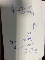
The worst condition is in the middle of the value of the pot
we have around 450 ohm of Zout + Xc of cap + 5 kohm that’s are in parallel with 5k that is in parallel with Zin of amp
If the pot is 10k
As I said posts ago
The picture of circuit is done now at Cairo airport waiting the plane for Amman. (For holiday)
we have around 450 ohm of Zout + Xc of cap + 5 kohm that’s are in parallel with 5k that is in parallel with Zin of amp
If the pot is 10k
As I said posts ago
The picture of circuit is done now at Cairo airport waiting the plane for Amman. (For holiday)
Attachments
- Home
- Amplifiers
- Tubes / Valves
- Input or Output Pre-amp Volume Control