You can get the ready to run (RTR) prebuilt BTSB Panel Mount version.
https://www.diyaudio.com/community/threads/rtr-btsb-panel-mount-buffer-gb.393118/#post-7254887
https://www.etsy.com/listing/137689...2619&click_sum=52643eb2&ref=shop_home_recs_34
https://www.diyaudio.com/community/threads/rtr-btsb-panel-mount-buffer-gb.393118/#post-7254887
https://www.etsy.com/listing/137689...2619&click_sum=52643eb2&ref=shop_home_recs_34
So I previously mixed up the 12VDC polarity when powering the module. Then the murata didn’t give proper voltages. I replaced that, get +/-15VDC from it, but have a distorted right channel. Dip switches work on the good channel, but not on the other. What should I start measuring to troubleshoot?
@von Ah
Did you check all the opamps (at the appropriate pins) to make sure they are all receiving +/- 15V? Do you have a copy of the datasheets of the two opamps you used in front of you to double check things (OPA1656 and LMEXXX)? Did you make sure that U5 and U6 LME opamps have the exposed DAP soldered perfectly to the pcb? Perhaps the dip switch needs a touch up?
If they passed, then…get a big copy of the schematic in front of you and study it. It’s pretty clear where the AC (music signal) is going.
Do you own a scope and function generator or better yet, a portable scope with integrated signal generator like what X had posted in this thread earlier? It’s a very useful tool and well worth the $$ if you don’t have a scope/generator already. Plus, it’s battery powered without a ground reference so it’s hard to destroy the scope (especially with bridged output stages, etc…).
If you don’t have a scope, no worries. Having a signal generator is very useful though, and you can even download it onto an iphone, play it on repeat, hook it up to the input of your buffer and use your DMM to do measurements with the DMM set to AC mode. Go to www.wavetones.com and download a 400Hz file (5 seconds long) and play it on repeat.
Divide the schematic into two parts. Before DIP switches and after DIP switches. Start somewhere. I usually start at the end and go backwards to find out where the signal is lost. Some folks start at the beginning of the circuit.
Sometimes it’s a cold solder joint. Sometimes it‘s a fried part. Does anything smell toasty?
Be careful with your leads when measuring, you don’t want them to slip and cause accidental shorts. Make sure your ground lead when ‘scoping around’ is firmly connected to signal ground on the board. Use mini-grabber adapters like the Pomona 4826. Since the parts are small, I would use a loupe to see where everything is or just wear my Yoctosun glasses (even though this is mostly a thru hole board that you built).
I would use a low voltage on the signal generator like 1V or less (I like 500mV). And set the dip switches to the 0 dB setting for starters.
You can start with measuring all the signal pins of the opamps in the channel that is not working and listing the voltages here with the signal generator ON. State which opamp it is obviously (i.e. U3, U4, U6, U7 since it is the right channel for you). And please post the schematic you used to build your buffer with voltages printed if possible. You posted a picture of your build here. Make 150% sure that all pins have enough solder and there are no cold solder joints. In the pic, I see a few areas that look as though there is no solder but that might be because you soldered from the bottom.
I’m sure X or jhofland have more poignant/detailed advice. Welcome to troubleshooting.
Best,
Anand.
Last edited:

Hi VonAh,
Anand has good advice. Reversed polarity on the PSU input might damage the DCDC converter but rarely, the stuff downstream. It might be bad solder joint or incorrect component (resistor etc). Or electrolytic cap polarity flipped.
Please post some closeup photos.
Anand has good advice. Reversed polarity on the PSU input might damage the DCDC converter but rarely, the stuff downstream. It might be bad solder joint or incorrect component (resistor etc). Or electrolytic cap polarity flipped.
Please post some closeup photos.
Thank you both!
I have no scope, but capable meters and mini grabber probes. I’ll pour over all the solder joints with magnification. And yes, while some of the joints look poor or missing from the component side, I did solder those from the other side. I’ll post photos and measurements tomorrow. With any luck, it’ll just be a cold joint. I used the V1.2 schematic with the corrected crossed resistors while I was building, but didn’t measure voltages past the regulator yet.
I greatly appreciate your time, consideration, and suggestions. This is such a great community.
I looked over the soldering and touched up any suspect joints. Progress! The right channel came alive and the dip switches work for different gain settings, but there is still trouble: the music will play fine for a bit, but then will start distorting in both channels after a minute or so. There is a rhythmic popping that starts. I’ll keep looking and get measurements at the ICs.
It sounds like you may have too weak of a wall wart power supply and that is going into hiccup mode. Try to find at least a 1000mA 12vdc wall wart. A linear Class 2 one is even better. Or you may have a small solder bridge short to ground of the +/-15v output. Or a small short to ground at the output. It’s causing the DCDC converter to become overloaded and go into hiccup mode and that’s the popping sound when the opamps get power cycled. Check you solder joints for small (microscopic) bridges. Clean flux and solder residue with paint thinner than alcohol, use an old toothbrush. Look especially closely where the +/- v rail pins on opamps are (corners).
Excellent advice, thanks. Thorough cleaning was high on the list of next steps. The SMPS is a 3A brick.
So if I was using this buffer to convert SE to Bal. What would be the input impedance? What impedance would I want upstream of this to feed it?
@wcwc
See post 313.
XRK states:
I would conservatively use a source that has at least 10 times less than that value. Some tube preamps that have high output impedances (few thousand ohms) may cause a little high frequency rolloff. Pretty much any digital source will be fine however.
Best,
Anand.
See post 313.
XRK states:
I think the nominal load is 50k ohm. Should be easy for most sources to drive.
I would conservatively use a source that has at least 10 times less than that value. Some tube preamps that have high output impedances (few thousand ohms) may cause a little high frequency rolloff. Pretty much any digital source will be fine however.
Best,
Anand.
Thanks, Anand.
The OPA1637 and LME49724 were designed to drive loads as low as 600ohms, the typical impedance used in balanced signal transmission.
The OPA1637 and LME49724 were designed to drive loads as low as 600ohms, the typical impedance used in balanced signal transmission.
hi to everyone here. I wanna start my build of the BTSB th version but sadly the
LME49724 is backordered. I was wondering if there is someone out there who has a 2 of them left from an earlier build and would be willing to sell them to me maybe? 🙂
LME49724 is backordered. I was wondering if there is someone out there who has a 2 of them left from an earlier build and would be willing to sell them to me maybe? 🙂
Alright problem solved thanks to a tip from a member here 🙂 Just found some at TI in case anyone else is in need.
I have these. They do not have an area on the underside for soldering to a PCB. I don't know if they will work. Isn't it a fake?
€ 2,40 5%OFF | 1PCS LME49724MAX L49724 SOP NEW
https://a.aliexpress.com/_mOfkU7c
€ 2,40 5%OFF | 1PCS LME49724MAX L49724 SOP NEW
https://a.aliexpress.com/_mOfkU7c
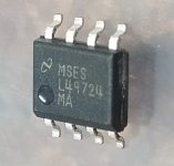
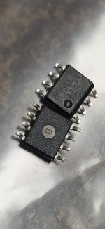
Even when these were made by National Semiconductor, the part always had a power pad since it is capable of sourcing 70mA of current. I don’t know what part they may have used to fake this but I don’t think it’s real. It may work as a double balanced opamp but you probably won’t get the ability to drive 52Vpp into 600ohms.
Hi question I am planning to use your BTSB buffer on my latest project but I don't have +-15v or 12v all I have is +24v so I was researching and do you thing I could replace the MEJ2D1215SC with NMK2415SC
Here is the link:
https://www.murata.com/en-us/products/productdetail?cate=cgsubPowerIsoDcDc&partno=NMK2415SC
Thanks a lot!
Here is the link:
https://www.murata.com/en-us/products/productdetail?cate=cgsubPowerIsoDcDc&partno=NMK2415SC
Thanks a lot!
Yes, that should work. Since it is from same company I would hope the +/-15v pinout is the same.
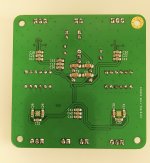
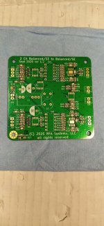
Hello everyone, friends. I am surprised how quickly the shipment from Texas Instruments arrived. Yesterday I soldered. It is a new experience for me, working with a hot air station. I hope I didn't screw anything up and BTSB will work. Thank you all for the instructions, advice...
Attachments

Peter,
Amazing job and looks like a pro did it. You are very good at this and I can see more SMT projects coming your way!
No flipping back and forth to insert leads into holes and no cutting leads afterwards. It actually is faster in many cases.
Good luck on operation but I almost would bet it works perfectly based on neatness.
Check R39 and touch up with a soldering iron tip on any spot you think might be a cold solder joint. All joints should have a rounded fillet of solder to show it fully wetted the part.
- Home
- Group Buys
- BTSB Buffer - SE/Bal to SE/Bal Buffer GB