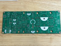
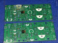
Synchronous rectification is by far better than any other rectifier solution, therefore I highly recommend it.
If you do not want to use evotronix.eu rectifiers, search forum for my open source THT version.
If you do not want to use evotronix.eu rectifiers, search forum for my open source THT version.
Of course there is!
Some don't know yet, don't have any project, and so on...
My next order of low ampérage bridges will be your universal
Some don't know yet, don't have any project, and so on...
My next order of low ampérage bridges will be your universal
Tibi,
...and the best replacement for Q8 (2N7000), is there anything better than ZVN4206?
Thank You!
...and the best replacement for Q8 (2N7000), is there anything better than ZVN4206?
Thank You!
Hello Tibi,Just confirmed to myself that FQA46N15 & IXTH48P20P make a better pair. Both have almost same Vgs(threshold) and transconductance.
Bass is deeper and amplifier get more control at any volume.
....
I am trying to understand why you chose the IXTH48P20P. I have searched for the parameters that make sense for the amplifier at Mouser and come up with the following type:
IXTH44P15T.
https://www.mouser.de/ProductDetail/IXYS/IXTH44P15T?qs=cvHLLyFtoE2pISjJk5x4ew==
I understand from the diagrams that this type is even more linear and very close to the parameters of the FQA46N15. Do I interpret this wrong? Or would you rate this similarly?
Is a Vgss of +-15V too low?
Do you know the differences between the two construction methods: PolarP and TrenchP
Regards Tim
There are several parameters that make a good "pair".
1. n and p mosfet must have same Vgsth. This is in range of -2V/-4V, on all three devices. Will slightly vary between production batches.
2. transconductance. n & p mosfet should have appropriate transconductance. You want simetric push/pull capability. Here IXTH48P20P have ˜32Siemens and FQA46N15 ˜36Siemens, while IXTH44P15T is ˜44Siemens.
3. Similar Ciss for n & p. IXTH48P20P have 5400pF and FQA46N15 ˜3200pF, while IXTH44P15T is 13400pF too high to make a pair with. \
Q17 run in class B, so Ciss is an important selection factor.
4. above Ciss is also translated in total gate charge. IXTH48P20P have 103nC and FQA46N15 110nC, while IXTH44P15T is 170nC.
Regarding "liniarity". These devices are high current and the area where we have interest is not presented in datasheet graphs.
There are other parameters to look for a good n&p mosfet pair, but these are the main that I looked for when I selected IXTH48P20P as "pair" for FQA46N15.
Another major selection factor, is availability of these mosfets. These days is harder and harder to make a n&p pair.
Now after more than one week with this pair, I must say there is no way to comeback at FQA36P15.
Last edited:
Stef,
Under what condition should the optional caps (22,24,25,27,29,30) be populated.
Thanks.
Under what condition should the optional caps (22,24,25,27,29,30) be populated.
Thanks.
Don't worry, Q17 will sound great with 36P15. Later you may look for other mosfet.And the Q17 journey begins…..
Tibi,
Your latest impressions about mosfets for Q16/Q18 has me thinking I wasted a lot of time getting very closely matched pairs of 36P15P’s

You may try exicon's lateral mosfet. These are more linear, have lower Ciss, higher Vds and come in better matched pairs.The availability of bipolar is not much better than that of mosfets. 😡
Beside this, you do not need protections. Their transconductance go sharply down with temperature, self-protecting them.
Downside, very low transconductance. This is translated in weak impedance control.
http://www.exicon.info/products.php#chartlink
I would go for double die ECW20N20 and ECW20P20. To integrate them in Q17, R14 and R15 must be reduced to 10ohm. R14 = 660ohm and R15=1k2.
These will fit an easy to drive speaker with SPL >90dBm.
They sound very good, with superb harmonics and soundstage.
Stef,
Under what condition should the optional caps (22,24,25,27,29,30) be populated.
Thanks.
C22, C24, C25, C27 = optional caps to add local power to mosfet. Never tried. For testing only. This technique is used in some amplifier designs.
C29, C30 : optional caps to reduce noise from led. I tried but saw no difference in measurements.
On the other hand, it is interesting to solder the opamp directly to the back of the PCB and to use C4' and C5' caps instead of C4 and C5 (use 100nF COG SMD caps).
Stef.
Good morning Stef,
The capacitors in parallel to the LEDs are to reduce background noise and that should be well below the measurement limit of an oscilloscope. You can hear such an effect, but there is hardly any measurement equipment with which you can measure such a effect properly, because it is really expensive.
I can achieve an effect to reduce the noise of the LED with Wima FKP2 4,7nF to 15nF. The small footprints (5 mm ?) for C22 - C27 can be fitted with Wima FKP2 33nF, this would compensate somewhat for the rough playing of the C18 and C19 - I haven't tested this combination yet, but think it is possible in principle that there is a sonic gain.
Regards Tim
Thanks for the optional cap info, Stef. I’ll probably leave them out now and tweak with them later.
Already have 100nF X7R caps installed at 4’ & 5’, I will install a DIP8 socket for easy opamp swaps. Then directly solder the smd opamp chosen under the board.
Already have 100nF X7R caps installed at 4’ & 5’, I will install a DIP8 socket for easy opamp swaps. Then directly solder the smd opamp chosen under the board.
- Home
- Amplifiers
- Solid State
- Q17 - an audiophile approach to perfect sound

