HI Guys
IRFD110 is not available in my city. I am getting IRFD110PBF from element 14. Will it work.
IRFD110 is not available in my city. I am getting IRFD110PBF from element 14. Will it work.
Thank You.
For 960 ohm resistor - Will use 976R // 56k which comes to 959R. I hope it works.
For IRFD110 will use IRFD110PBF.
Now I can start gathering components.
For 960 ohm resistor - Will use 976R // 56k which comes to 959R. I hope it works.
For IRFD110 will use IRFD110PBF.
Now I can start gathering components.
Last edited:
Have run through another problem.
Cant find LF411. What are the alternatives.
Also do the resistors need to be 1%.
Kindly guide.
Cant find LF411. What are the alternatives.
Also do the resistors need to be 1%.
Kindly guide.
You need single opamp. TL072 double opamp, it has different pinout.
Look for TL071, TL081, OPA134, UA741 etc. Prefer jfet inputs for lower offset.
Look for TL071, TL081, OPA134, UA741 etc. Prefer jfet inputs for lower offset.
I don't know much about electronics. I can solder well read schematic to some extent. I rely on instructions provided by more knowledgeable members.
Will look for given op amps.
Thanks
Will look for given op amps.
Thanks
I ve got two more question
1. Which transistor should I choose IRF530 N-mosfet or P-mosfet ?
2 what is decent amount of capacity uF per channel to avoid ripple ?
1. Which transistor should I choose IRF530 N-mosfet or P-mosfet ?
2 what is decent amount of capacity uF per channel to avoid ripple ?
1: IRF9530 and IRF530 are used in DOGCmk3 and 9630/630 at DOGC-H (stronger version.
2: it would be nice to use 4x 10 000uF in total,2x 10 000 per PSU rail.
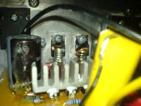
what You shoud really pay attention to - is to match as close as possible input IRFD110, and put a heatsink on both of them because they get heated quite a lot.
also - you must pay attention that those are mosfet-input transistors and they WILL blow up if you put more than +/-20V at the amplifier input (+/-20V is max. Ugs!) and that WILL happen it any static electricity comes to input of your amplifier. it is preventable if you use 12V zener in series with 1N4148,then make another same example,connect it anti-parallel and soldier that on amplifier input connectors.
2: it would be nice to use 4x 10 000uF in total,2x 10 000 per PSU rail.
what You shoud really pay attention to - is to match as close as possible input IRFD110, and put a heatsink on both of them because they get heated quite a lot.
also - you must pay attention that those are mosfet-input transistors and they WILL blow up if you put more than +/-20V at the amplifier input (+/-20V is max. Ugs!) and that WILL happen it any static electricity comes to input of your amplifier. it is preventable if you use 12V zener in series with 1N4148,then make another same example,connect it anti-parallel and soldier that on amplifier input connectors.
Attachments
![DOGC-povezivanje[1].gif](/community/data/attachments/1063/1063239-d50b53664618268622b2f610ead986ba.jpg?hash=1QtTZkYYJo)
![ind[1].jpg](/community/data/attachments/1063/1063243-0aa4f127a0e626701a2c4a63ae962e30.jpg?hash=CqTxJ6DmJn)
![MyDOGC1[1].jpg](/community/data/attachments/1063/1063244-74cba248cd381946ee027c050b648de4.jpg?hash=dMuiSM04GU)

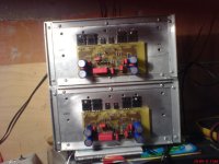
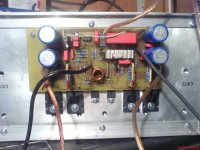
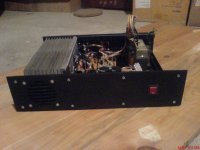
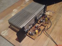
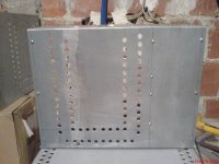
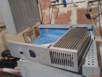
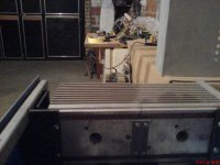
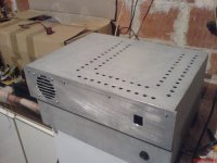
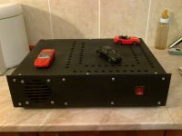
DOGC-H (i have them both made)
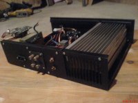
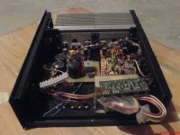
for BOTH versions you should provide beefier heatsinks because quiescent current is set to about 200mA,so you will have 10W of heating on mk3 or 20W on H version,even in idle. but,amplifier will not get heated much more even at moderate output power.
it is a nice sounding amplifier with a warm sound,both mk3 and H versions.
Attachments
![ind[1].jpg](/community/data/attachments/1063/1063249-0aa4f127a0e626701a2c4a63ae962e30.jpg?hash=CqTxJ6DmJn)


...and some more...
Attachments
-
 Slika148.jpg198.3 KB · Views: 118
 -
 DSC01334.JPG424.5 KB · Views: 100
 -
 DSC01333.JPG418.2 KB · Views: 96
 -
 DSC01332.JPG429.5 KB · Views: 106
 -
 DSC01330.JPG453.3 KB · Views: 115
 -
 DSC01327.JPG472.8 KB · Views: 123
 -
 DSC01326.JPG441.9 KB · Views: 126
 -
 DSC01325.JPG458.7 KB · Views: 127
 -
 DSC01323.JPG461.2 KB · Views: 124
 -
 DSC00021.JPG406.4 KB · Views: 121
 -
 DSC00020.JPG454.8 KB · Views: 107
 -
 DSC00017.JPG480.8 KB · Views: 115
 -
 DSC00016.JPG403.7 KB · Views: 108
 -
 Slika146.jpg184.4 KB · Views: 113
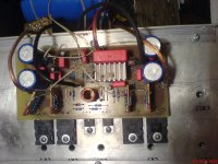
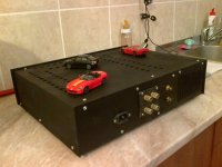
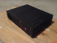
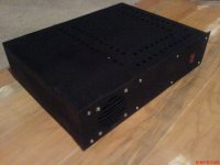
thanks a lot for explanations and building tips !!!!!!actual pictures of my DOGC"s:

is voltage of pair BC549/BC559 30V is sufficient ? because original BC550C- 560C is 50V ? unfortunately BC550C/BC560C is discontinuedDOGC-H (i have them both made)
- Home
- Amplifiers
- Solid State
- DOGC-H by Dr. Jagodic