In practice the jfets see less than half the rail and this is bootstrapping to the output, so you can run higher rails safely.
😎
😎

Thanks Nelson - now wondering, in addition to BA3, strapping an F8 to an F4... anyone done it yet?In practice the jfets see less than half the rail and this is bootstrapping to the output, so you can run higher rails safely.
😎
F9 (Axpona?) - exciting times...
The SLB has about 3v drop at max ripple reduction setting. When sizing a trafo, I usually size 2-3x larger than steady current needed. The trafo also has voltage sag due to class A load.- Jan Dickinson superegulator needs 5v drop
- XRK971's Smooth like Buttah power supply I'm using also has a 5-6v drop.
F4 default power supply is 18vac giving typically +/-24vdc. Perhaps I'd be better off running 26vac secondaries, then both the SLB and super regulator (with it's own rectifier and cap bank) would give some 28vdc into both the F4 and BA3?
How's that sound? Probably a gain of about 20dB from BA3?
Assuming you want 24vdc at the amp rail, usually a 22v trafo is needed. Assuming you need 2.5A x 24v x 2 rails - this is 120VA requirement. So 2x would be 250VA to 300VA trafo per channel. So two 250VA to 300VA trafos for dual mono or a single 500VA to 600VA with quad secondaries for two SLBs.
Work out the voltage AC needed going backwards from 24v requirement at amp. Add 3v for SLB dropout. Add 3v sag at Class A or 6v. So that’s 30vdc and divide by 1.41 we get 21.3vac. Always go up in “shoe size” or size 22vac. 🙂
You can always burn off a little more voltage with a larger value R in the CRC. But if lacking raw you can’t get enough and amp will be under-powered.
No.How's that sound? Probably a gain of about 20dB from BA3?
Page 6 from the BA3 writeup:
The voltage appearing at the Gate of Q3 is amplified by something less than the ratio of R10 divided by R8, and with the same happening at Q4 and considering the transconductance of the Mosfets, comes out at about 15. Both of them added make a system voltage gain of about 30X, or 30 dB.
And...
The supply voltage is only critical with respect to the voltage rating of the input JFETs, which are nominally 25 volts. In actual testing, they break down around 40 volts. I wouldn't worry about running them as high as 30V. Hot-rodding this circuit would likely involve cascoding the input Jfets to allow higher voltages.
Best,
Anand.
BA3 FE ....... with original values and Toshiba mosfets, gain is rather around 10V/V, +20db, as far as I remember
figures from Papa's article are somewhat funny, but we know that from time of publishing
anyway, best to measure it when built, easy to alter for specific needs, just changing I/V loading resistor (330R originally)
figures from Papa's article are somewhat funny, but we know that from time of publishing
anyway, best to measure it when built, easy to alter for specific needs, just changing I/V loading resistor (330R originally)
Easy to build and measure. Let us know stretchneck, I’m curious as the BA-3 has been on my sights for a while. The F4 gives us endless possibilities. At first I thought about making an ‘integrated F4‘, i.e preamp within F4 but now, I think I’d rather have a ‘solid state voltage gain stage box’ with a +/- V power supply where I can pop in/out various linestage topologies, i.e. Wayne’s BA2018, BA3FE, DIY2022FE, X’s Aksa Lender, etc…
Coda’s system 1/2 is basically a single box that contained a gain/Vas stage and then another pair of boxes with source follower topology amplifiers. It’s a great idea and F4 can be adapted as such. The modern one is now called S150/250.
Sorry for rambling…all is possible for the FAB network!
Best,
Anand.
I agree.... I want a BA3B independent of the F4 (s) it's going to drive... because I might use it to drive the A2s, A5s etc... that gives me a lot of flexibility.
Hi An
That was our thinking when we made the M2X brass stand-off mount compatible preamp line stage. It allows one to swap line preamp modules and choices included among others: Pass ACP+, Pass H2, Wayne’s Burning Amp 2018, Pete Millet Korg Nutube, and several designs by Aksa. Many were Class A designs and more recently the modules include high voltage opamps capable of swinging 70Vpp.
Hi Anand,Easy to build and measure. Let us know stretchneck, I’m curious as the BA-3 has been on my sights for a while. The F4 gives us endless possibilities. At first I thought about making an ‘integrated F4‘, i.e preamp within F4 but now, I think I’d rather have a ‘solid state voltage gain stage box’ with a +/- V power supply where I can pop in/out various linestage topologies, i.e. Wayne’s BA2018, BA3FE, DIY2022FE, X’s Aksa Lender, etc…
Coda’s system 1/2 is basically a single box that contained a gain/Vas stage and then another pair of boxes with source follower topology amplifiers. It’s a great idea and F4 can be adapted as such. The modern one is now called S150/250.
Sorry for rambling…all is possible for the FAB network!
Best,
Anand.
That was our thinking when we made the M2X brass stand-off mount compatible preamp line stage. It allows one to swap line preamp modules and choices included among others: Pass ACP+, Pass H2, Wayne’s Burning Amp 2018, Pete Millet Korg Nutube, and several designs by Aksa. Many were Class A designs and more recently the modules include high voltage opamps capable of swinging 70Vpp.
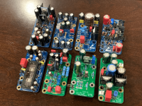
Attachments
I'm taking silence as golden and pressing on. See if it'll be an interesting experiment. Need to measure the bias voltages on the older amp before I get too far in the swap.
Easy to build and measure. Let us know stretchneck, I’m curious as the BA-3 has been on my sights for a while. The F4 gives us endless possibilities. At first I thought about making an ‘integrated F4‘, i.e preamp within F4 but now, I think I’d rather have a ‘solid state voltage gain stage box’ with a +/- V power supply where I can pop in/out various linestage topologies, i.e. Wayne’s BA2018, BA3FE, DIY2022FE, X’s Aksa Lender, etc…
Coda’s system 1/2 is basically a single box that contained a gain/Vas stage and then another pair of boxes with source follower topology amplifiers. It’s a great idea and F4 can be adapted as such. The modern one is now called S150/250.
Sorry for rambling…all is possible for the FAB network!
Best,
Anand.
That is what I am working towards. I just received Slagle autoformers today. I plan to make a passive switch box/volume control with an autoformer and the switch board from the Yarra. Also have a Tortuga board I could use in a different switchbox/volume control. After the volume control switchbox I will have the ability to to insert an active preamp of some sort. I have the Yarra pcb and all the modules to populate, Whammy, and an iFi Itube2. Could also make a BA3 preamp. Preamps are being built as SE 1 channel input and output without volume control. This should allow me to try a bunch of different options. Then it goes into a 6-24 active crossover followed by BTSB buffer to convert SE to balanced to my 2 way FAST speakers.
So the "best" preamp into a current gain amplifier like the F4 would be a unity gain active buffer followed by a TVC?
https://www.passivepreamp.com/
How about a B1 with a simple autoformer? I just ordered some Elcor transformers... I don't know if they'll swing enough voltage though.
https://www.passivepreamp.com/
How about a B1 with a simple autoformer? I just ordered some Elcor transformers... I don't know if they'll swing enough voltage though.
While an buffer-autoformer is said to be the best volume control, to drive a F4 you rather „need“ a preamplifier resembling a small poweramplifier (like a flea-amp etc. …)
At least that’s how I understood it…
At least that’s how I understood it…
My understanding is that you need a voltage amplifier. The input impedance of the F4 is high enough that it won't draw much current so it won't be hard for the preamp to maintain its voltage level.
So, the autoformer will amplify the voltage...
What will the autoformer do to the output current needs of the preamp? If the autoformer has a 5 to 1 gain... if the power is the same on both sides of the autoformer (input and output) that means the current must change, huh? If P=IV, then if the voltage increases by 5, then the current on the output side of the autoformer will be 1/5th that of its input. I figure that an transformer of any kind only affects the voltage levels, not the power levels... I could be wrong but since they are passive devices, I see no way it can break the Laws of Conservation of Energy, et al...
So, I figure when using an autoformer between the active preamp buffer (or source output) and the F4 amp... the preamp won't see a difference on the load it sees at the autoformer and happily will put some power into it... with a given voltage and current associated with that power. So long as the load of autoformer is not too low this will work. Obviously, if the input impedance dropped very low, you would need one very stout preamp... hence your flea powered amp.
Bottom line, I think the reason why people say you need a flea powered amp to drive the F4 is because most preamps just don't have enough voltage amplification. If you can swing 15-Vrms into the F4 you ought to be OK.... my CJ PV9 does it fine.
Hmm, I found it.. I was correct about the power. The power is pretty much the same across both sides of the transformer, minus some losses in the wiring...
"The presence of a transformer can alter the impedance seen by a voltage source. This is not too surprising when we consider that impedance is related to voltage and current and that a transformer with N ≠ 1 alters the voltage across and current through a load component on the secondary side. It turns out that a voltage source on the primary side of a transformer sees an impedance of Z divided by N2 on the secondary side, where Z is the physical impedance of the load component and N is the turns ratio."
https://eepower.com/power-electroni...ansfer/understanding-electrical-transformers/
So, there is a price to pay for using a transformer...
The same applies to the autoformer:
https://www.tubecad.com/2018/09/blo...e ratio is equal,the autoformer, i.e. 32 ohms.
Neat stuff actually. So you do need a strong voltage source.
Time to experiment, first to try the B1K into the F4... second when I get the transformers will play with the B1.... but, I honestly don't want to put my F4 at risk... hmm... what should I do first... what kind of a load should I use?
Everything I understand on driving an amp, a voltage amplifier is needed, whatever it looks like. The input impedance of the F4 is 47k Ohm, an easy load. I would think a design around a high mu tube like a 12AX7 or similar would do fine in meeting the objective.My understanding is that you need a voltage amplifier. The input impedance of the F4 is high enough that it won't draw much current so it won't be hard for the preamp to maintain its voltage level.
Bottom line, I think the reason why people say you need a flea powered amp to drive the F4 is because most preamps just don't have enough voltage amplification. If you can swing 15-Vrms into the F4 you ought to be OK.... my CJ PV9 does it fine.
I'm not sure where people have stated a small power amp is needed. All the documentation from NP points to a want of a small DHT amp to get the sonic signature of it and seems like overkill from a current perspective.
if needed, Rin of F4 can be altered, say up to 220K, without penalties
just increase value of 47K resistor at input
just increase value of 47K resistor at input
- Home
- Amplifiers
- Pass Labs
- A guide to building the Pass F4 amplifier