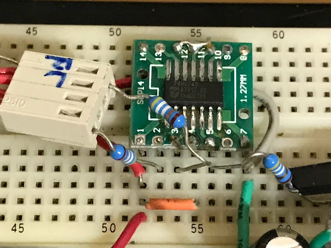
A Philips 74HC74 soic.
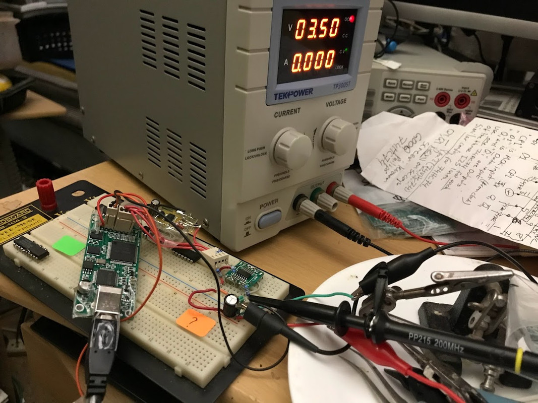
Re-clocking the BCK line on the same breadboard test jig used prev.
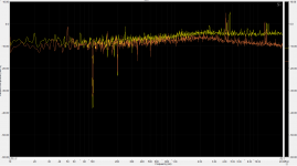
Un-clocked (BCK) straight out USB adapter:

Re-clocked (BCK) using Philips 74HC74 soic, manuf 2005 (as shown):

Re-clocking the BCK line on the same breadboard test jig used prev.
Un-clocked (BCK) straight out USB adapter:
Re-clocked (BCK) using Philips 74HC74 soic, manuf 2005 (as shown):
These oscillograms are meaningless. You can visualize the jitter by lowering the time base so that you can see something like 50 periods. Then turn on 10x horizontal magnification (increase brightness if necessary) and shift to the end of the signal. Now you can see several leading or trailing edges, smeared. That is they will change state at different time, a bit sooner or a bit later. That is jitter.
I am thinking about creating a simple demodulator that converts phase noise to amplitude noise. Similar to an FM demodulator.
I am thinking about creating a simple demodulator that converts phase noise to amplitude noise. Similar to an FM demodulator.
Are you measuring the jitter of your oscilloscope timebase, of the oscilloscope's trigger circuit or of the crystal oscillator + reclocking circuit with that method? I'd expect the first.
The jitter of the oscilloscope's timebase and triggering do not play any role here. Think about it. For example the leading edge of the measured signal triggers the horizontal deflection. From that point the horizontal deflection runs independently. Some 50 signal periods later this is repeated. The measured signal around the end of the horizontal deflection will arrive a bit sooner or later than those in the previous horizontal deflection periods.
This is just a visualization, not a measurement.
This is just a visualization, not a measurement.
Does the signal arrive a bit sooner or later than in the previous sweep or is the sweep itself a bit faster or slower? At least with the old-fashioned analogue scopes I am used to, the sweep speed is set by an RC product, while the clock signal under test depends on a much more stable crystal oscillator.

I expect that when philipsmarantz tries that with the signals of post #61, there will be no noticable difference.
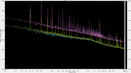
Few years ago I made some test with jitter measurements. But this was relative jitter test
The goal was to explore the influence of some "black box" circuit (DUT).
Signal from very good oscillator goes to the DUT input and also divided by2 to one test input input as a reference.
DUT output through isolated transformer (1:1) and divided by 2 goes to the second test test input.
So both signals, DUT and the reference were produced from one oscillator.
Test circuit was simple XOR gate, High Pass filter to avoid the DC component and Low Pass Filter at the output.
Output was connected to the sound card (ADC) input, and Spectrum Analyzer software run on PC.
1st test was without DUT and making the loop (connect the test board output to it's input) - this was the reference spectrum.
After that I measaure the spectrum with different DUT - some kinds of the cables, with different length, spdif/ethernet transformers, digital isolators, etc.
With this test boars I cannot measure oscillator's jitter, just the influence of the DUT. But it helps.
Attachments
I use an old analog scope, the make and type is unimportant. I will try and get some screenshots.
Iwatsu SS-5321S
Sweep accuracy: +/- 2% (over center 8 divisions), +/-5% (over any 2 divisions within center 8 divisions)
I think this is the deviation from the actual ns/div (or us/div, ms/div, s/div) setting, not the linearity specification.
But I think any 10 MHz or better analog scope would do, provided it has 10x sweep magnification.
My Tek 465 is all original AFAIK. All orig caps, etc.
I usually let it "warm up" for about 1/2 hr before use.
About the experiments and photos ... keep things simple as per my original design for thread.
I simple keep things (settings, components) similar except for that IC on the breadboard.
Just use an iPhone and try to frame the Tek screen for similar image captures (working on all this analog, hand-held skilling).
Even given the crudity of all these "techniques", you can see a lot into ... the dream. The magic is right there in plain sight.
Just tried the in-line RCR network Arcam used in certain CD player models/dacs from early 90s (???).
See: Alpha 5 (serv. man. p 10) https://www.hifiengine.com/manual_library/arcam/alpha-5-cd.shtml
Used the RCR as per Arcam schematics, on MCK (in), BCK (Data, in) and Out (Data)
The BCK waveform -- Data out -- looked worse after using this network. See yesterday's post with photos of clean, "ideal" waves.
I didn't spend too much time tweaking this RCR setup. E.g., using only one or two lines with RCR.
Arcam has tried other approaches, such as relatively "high" in-line Rs (390 ohms). So I may set that up some time.
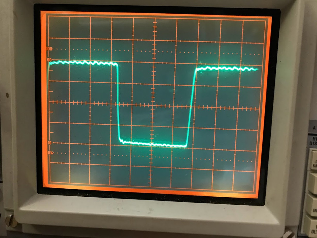
Had some Vishay Dale 0.5 w 100R's around. And substituted these in for the prev. Yageo MFR-25FBF52-49R9.
Yes, this did further clean up the BCK re-clocked out of the soic Philips 74hc74.
Not sure about what subjective diffs may be. That is, stuff we hear in the dream but have yet to quantify with 'scopes and such.
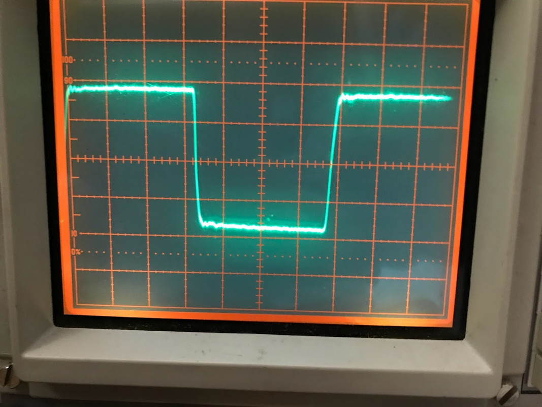
BCK (USB adapter ; raw BCK out; no reclock)
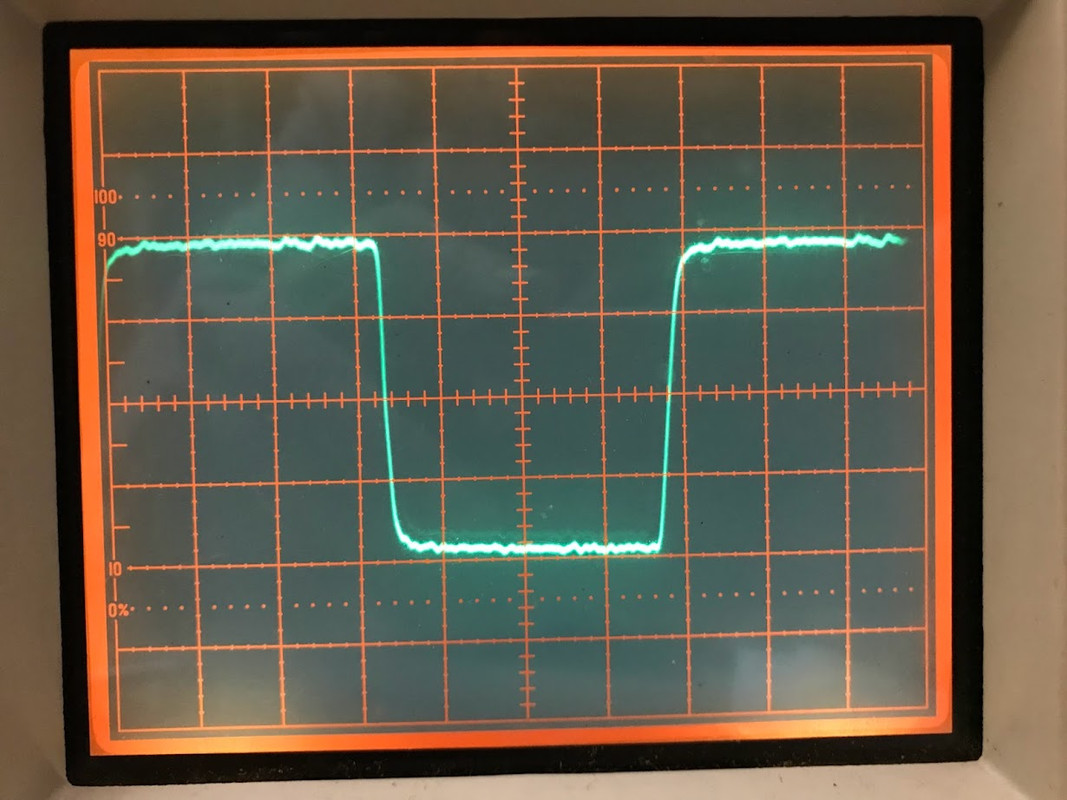
BCK (USB adapter ; reclock 100R)
BCK (USB adapter ; reclock 49R)
Yes, this did further clean up the BCK re-clocked out of the soic Philips 74hc74.
Not sure about what subjective diffs may be. That is, stuff we hear in the dream but have yet to quantify with 'scopes and such.
BCK (USB adapter ; raw BCK out; no reclock)
BCK (USB adapter ; reclock 100R)
BCK (USB adapter ; reclock 49R)
philipsmarantz, you really think that you can see a jitter with modern requirements, with analog scope,
designed 50 year ago? Tek-465 is a very good scope, bit not for this.
I'm not interested in jitter.@philipsmarantz, you really think that you can see a jitter with modern requirements, with analog scope,
designed 50 year ago? Tek-465 is a very good scope, bit not for this.
And I've never contextually "thought" about it -- nor pushed that as a characterizing agenda or criteria in this thread. I've noted this to you previously. Not sure why you keep bringing up the issue?
That said: Jitter can be high or low on certain systems but not necessarily correlated with "better" sonics or fidelity. Zero-OS dacs, e.g., have high measured jitter ... but their characteristic, subjective fidelity remains high.
I'm not interested in jitter.
...
Not sure why you keep bringing up the issue?
Because the goal f re-clock is elimination of the source signal jitter. Nothing else.
Zero-OS dacs, e.g., have high measured jitter ..
There is no connection between jitter and so-called "Zero-OS dacs".
- Home
- Source & Line
- Digital Line Level
- Re-clocking I2S (simple version)