Hmm, technically, for the record 😉: Fs = 35, Qms = 2.93, Mmd = 32.93, Bl = 9.68 😉.
Also FWIW, a max flat tuning assuming zero added resistance (Rg) = 0.42*35*0.46^-0.96 = ~31 Hz
Also FWIW, a max flat tuning assuming zero added resistance (Rg) = 0.42*35*0.46^-0.96 = ~31 Hz
Correct, initially I inserted the Bl amount into the Vas field. Corrected in the last post with graphs
Lol, man I don't know enough to understand the second line numbers. Some help with that please
Lol, man I don't know enough to understand the second line numbers. Some help with that please
Latest iteration cab external approximate W 170 cm x H 56 cm x D 41 cm
Does the graph look good enough to build? I really don't know how to interpret this. Or should I go back to the last one posted?


Does the graph look good enough to build? I really don't know how to interpret this. Or should I go back to the last one posted?
Attachments
Last edited:
Be nice to see a plot with damping, all the ripple in the unstuffed line makes the graph hard to interpret. Are you adjusting the Zd to kill the first unwanted harmonic?
dave
dave
Learning a lot from reading these threads, so I don't want to derail anything, but could I ask a quick question about this? Is this aperiodic loading different than the critical damping and the "click-test"?Let's take a 15 litre (approximately 0.5 cu ft) enclosure as an example.
To convert this otherwise sealed enclosure to aperiodic loading, you can drill a 5 x 5 array of 12 mm (0.5") holes in the rear of the enclosure.
The centres of the holes shall be 20 mm (0.75") apart and be covered internally with soft, felt like cloth to provide extra acoustic resistance.
With this design, only the internal walls of the enclosure (excluding the front and back) should be lined with absorbent material.
The reason I am asking is I tried the critical damping click test twice (once without a measuring microphone, and later on another speaker with a microphone), and didn't have much luck*. Then I saw another reference where the critical damping specified silk tightly stretched over the vent, and realized I had done it wrong by using cotton batting placed over (vice stretched tightly over) the vent.
* Half understanding what right sounded like, and half there were probably a lot of other things wrong with what I was doing (box tuned to lower than .707*Fs, focused mostly on power response, not understanding what to look for in the impedance or other graphs, etc.).
The idea of aperiodic loading is to reduce the magnitude of the impedance peak at resonance to a minimum.
The density of the resistive membrane can be altered to achieve maximum damping.
Measuring the impedance around the resonant frequency will give you a visual indication of when the damping is maximised.
The density of the resistive membrane can be altered to achieve maximum damping.
Measuring the impedance around the resonant frequency will give you a visual indication of when the damping is maximised.

Be nice to see a plot with damping, all the ripple in the unstuffed line makes the graph hard to interpret. Are you adjusting the Zd to kill the first unwanted harmonic?
dave
Zd? Is that driver offset? I have set to 3rd by using the OD (offset driver)
I will try with damping
I am having trouble with this. Are you able to help with the stuffing?Be nice to see a plot with damping, all the ripple in the unstuffed line makes the graph hard to interpret. Are you adjusting the Zd to kill the first unwanted harmonic?
dave
Dave
Is this what you meant? I pulled the stuffing sliders to the middle position. Any recommendations, or is that a bad graph?

Is this what you meant? I pulled the stuffing sliders to the middle position. Any recommendations, or is that a bad graph?
To design a conventional transmission line loudspeaker system using Hornresp:
1. Specify the driver parameter values.
2. Open the TL Design tool and choose the method and area taper / expansion ratio that gives results that best match the desired design goals.
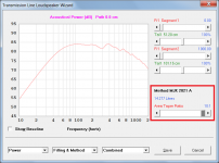
To illustrate, the attached example uses Martin King's 2021 method with alignment SBB4 / BB4 / QL =15 and an area taper ratio of 10:1. The Epique driver parameter values given in Post #103 have been used. The design goal was to minimise the system size while retaining reasonable performance. The system volume for the design shown is 14.277 litres.
1. Specify the driver parameter values.
2. Open the TL Design tool and choose the method and area taper / expansion ratio that gives results that best match the desired design goals.
To illustrate, the attached example uses Martin King's 2021 method with alignment SBB4 / BB4 / QL =15 and an area taper ratio of 10:1. The Epique driver parameter values given in Post #103 have been used. The design goal was to minimise the system size while retaining reasonable performance. The system volume for the design shown is 14.277 litres.
Attachments
Thanks man, will doThat is a whole lot better. Turn up until most of the ripple is gone.
dave
David
Thanks man. I am getting those results but increasing segment number to try to meet cab dimension goals. My last posted graph is with 4 segments. How does that compare with your pic? I am not able to determine if it gets bad as I do not have enough experience to make those calls
Thanks man. I am getting those results but increasing segment number to try to meet cab dimension goals. My last posted graph is with 4 segments. How does that compare with your pic? I am not able to determine if it gets bad as I do not have enough experience to make those calls
My last posted graph is with 4 segments. How does that compare with your pic?
I used 2 segments in my example to keeps things simple but there is no problem in using 4 segments if you wish.
Greets!Were you able to run this again. I somehow ended up getting even better results for the cab size, but do not know how to really read the audio graphs to interpret the results. Do you have any opinions on the last graph that I posted?
You're welcome!
Such as? I mean I just saw some things that needed correcting and even then forgot to change 'pathlength' to something closer to what you'd hear in room/listening position and how it affects any damping choices, not to mention what it does to LF gain BW when wanting to under size.
If you mean your tapered one, it looks OK at a glance.
I was pointing out that a max flat alignment for your driver assuming no added series resistance to increase Qts is ~31 Hz Vs your mildly under damped ~34 Hz.Lol, man I don't know enough to understand the second line numbers. Some help with that please
Margolis-Small's HP 67/97 & 41C calculator program if wanting all the math for vented, sealed: http://www.aes.org/e-lib/browse.cfm?elib=3902
Vented net volume (Vb) (L) = 20*Vas*Qts'^3.3
Vented box tuning (Fb) (Hz) = 0.42*Fs*Qts'^-0.96
F3 = Fs*0.28*Qts^-1.4
(Qts'): (Qts) + any added series resistance (Rs): http://www.mh-audio.nl/Calculators/newqts.html
He can't as long as he is designing based on 1/3 folding because its long vent is otherwise misaligning it.Are you adjusting the Zd to kill the first unwanted harmonic?
That last iteration is 4 segments. Is that still 1/3 folding by ratio? I made a table to take the segments off like this and entered into HR. That tuned too low, so shortened until segment length was 55 cm. Now, I did notice that I can't move the driver by specifying a length in cm. Does that mean I also can't physically change driver position on the face?
Keep in mind that the driver will be going on the long face, as I will be standing the box over so that the segments run vertical. Making a pipe tuned to 34hz just to test the Pioneers and other likely drivers. The Epique was just a pick for modelling as it has similar dimensions and response. I did 4 different drivers in this HR dat file. In the same box, all showed the same tuning frequency. This tells me that my guess that the tuning of the pipe is a feature of the pipe is rightish. Even if you blow into it, it should still be 34hz tuned. I then don't understand this requirement to have driver specs to tune the box to a particular frequency
If I have done the maths and ran the program correctly, then I am guessing that I should be somewhere close to my target. This is where I am at with that last graph. If this looks ok as a 34hz pipe, I am then ready to cut some MDF tomorrow morning
34hz chosen as Fb for pipe
34000 cm per second / 34hz = 1000 cm. 1000 / 4 = 250 cm
3 segments = 250 cm / 3 = 83.33 cm
S1: 100% = 136.10 cm2 = 14.4 cm x 9.45 cm
S2: 83.5% = 113.64 cm2 = 14.4 cm x 7.89 cm
S3: 67% = 91.19 cm2 = 14.4 cm x 6.33 cm
S4: 50.5% = 68.73 cm2 = 14.4 cm x 4.77 cm
S5: 34% = 46.27 cm2 = 14.4 cm x 3.21 cm
Segment internal length after taper reduction 55 cm
Internal width 14.4 cm (driver cutout limited)
Resulting cab internal dimensions W 14.4 cm x H 59 cm x D 31.14 cm
Table to take of numbers
Not acoustically; in the sim, correct, though of course you can physically, so locating it 48 + 38 = 86 cm down from the top (i.d.) will null out the notch. Right, no need for driver specs per se to design any type of speaker box, but as I showed from math, you're misaligning the pipe tuning WRT the driver's specs.
- Home
- Loudspeakers
- Multi-Way
- Desktop TL template audio discussion