A high quality rotary will not degrade the sound, I got excellent result using Grayhill rotary switch!
Grayhill 44A45-04-2-04N SWITCH ROTARY 4POS
BTW, you can combine a few toggle switch work as DIP switch to get the job done.
Grayhill 44A45-04-2-04N SWITCH ROTARY 4POS
BTW, you can combine a few toggle switch work as DIP switch to get the job done.
Last edited:

I didn't know Greyhill made rotary switches with 5 ampere ratings 🙂
Same for DIP.
I would just use a 1pst switch to switch a relay.
You can get the 12V you probably would need from the heater winding for like 50 cents worth of parts (2 diodes, and 2 caps to make the Delon).
I use these in my speaker switch boxes...
https://www.digikey.ca/en/products/detail/phoenix-contact/2903676/5199620
Thanks for the suggestion of this switch. I’ll have a think. Maybe for now, it’s more sensible to try to keep it simple just to stick to 4/8 ohms with a 3PDT toggle switch. Cheaper and less wiring that I might accidentally wire incorrectly! Going to a 6 pole 3 position rotary for 16/8/4 ohms looks a lot more complicated (and I’m sure 16/8/4/2 is more complicated and also means an even bigger rotary switch)A high quality rotary will not degrade the sound, I got excellent result using Grayhill rotary switch!
Grayhill 44A45-04-2-04N SWITCH ROTARY 4POS
BTW, you can combine a few toggle switch work as DIP switch to get the job done.
These big rotary switches do look pretty big. I will check but there might not be quite enough space too.
Thanks for this info, looks like an option but I’d be worry I’d mess this up! Never done anything like that before (getting 12V fromI didn't know Greyhill made rotary switches with 5 ampere ratings 🙂
Same for DIP.
I would just use a 1pst switch to switch a relay.
You can get the 12V you probably would need from the heater winding for like 50 cents worth of parts (2 diodes, and 2 caps to make the Delon).
I use these in my speaker switch boxes...
https://www.digikey.ca/en/products/detail/phoenix-contact/2903676/5199620
View attachment 1145641
the heater winding etc), so it’s probably just best to go with a toggle or rotary switch for now and keep it more simple. Less things to go wrong!
The output transformers in these amps with these 4 different outputs were made by Electraprint and are supposed to be very nice quality.
I will put up another thread soon asking for ways I can upgrade/alter these Welborne 300B amps. They are the top “Terraplane” version with virtually all film caps (including an all film cap PSU) They are a bit different to a typical 300B SET design and are direct coupled. There is only one series resistor in the “signal” path between input and output. They also use an “Ultrapath” cap instead of a Cathode bypass cap on the 300B section.
BTW, you can combine a few toggle switch work as DIP switch to get the job done.
😎
Thanks a lot for this. It I did that how many of the impedance from the transformers taps could it be used for?
I’ve been looking at 3PDT miniature toggle switches. I have a 4PDT with same lug spacing at the solder points as the common side 3PDT/ you can buy. The solder points are so close together. Might be too close to be useable. I can see what you guys meant about it being easy to solder a rotary switch, so maybe I should consider one, for 16/8/4 ohms or maybe even going all the way to 16/8/4/2 and just get it all done and out of the way so the amps then have max flexibility
I’ve been looking at 3PDT miniature toggle switches. I have a 4PDT with same lug spacing at the solder points as the common side 3PDT/ you can buy. The solder points are so close together. Might be too close to be useable. I can see what you guys meant about it being easy to solder a rotary switch, so maybe I should consider one, for 16/8/4 ohms or maybe even going all the way to 16/8/4/2 and just get it all done and out of the way so the amps then have max flexibility
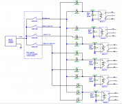
Hi, diode switching of relays is always an option for a task like this, I have drawn up an example of how diode switching is implemented, one could modify a cheap multiple relay PCB purchased from Ebay.
If not into microcontrollers one could cut off the electonics from a PCB like this and add some diodes to a rotary switch.
https://www.ebay.com.au/itm/334515620311?hash=item4de2af49d7:g:3-0AAOSwHVJi4yAv&amdata=enc:AQAHAAAA4GrOBweiMdLBJ1BbrZ6XKlc3JzKqddEVl2ARUd/gHsulM11mhdQ/LyUohgABc2ayodc5sgqqGK5zDrL7os3YSJtPS4jmaxQmZzvl5V3VLVCgT/7c+yfeCMLFuYwShZxviTX69sN8u47NsXQyoXrPNWBgPBns2QfmMCtnWscAb524IfkdRxADyzObKtfrPN3rn/+ei5M8tPxEHc3OYUkXGN2zCUw1LqABVjm/NBfU2YRV74lMRH5/q5oWFBqX9vFR9y52qwtrAFnCNqekalJhxB7fU0EUWmD14wSKQj2aWsNx|tkp:BFBM2JC2kdBh
Ken K
Attachments
Sorry for the delay in replying to this. Had a busy few days.Hi, diode switching of relays is always an option for a task like this, I have drawn up an example of how diode switching is implemented, one could modify a cheap multiple relay PCB purchased from Ebay.
If not into microcontrollers one could cut off the electonics from a PCB like this and add some diodes to a rotary switch.
https://www.ebay.com.au/itm/334515620311?hash=item4de2af49d7:g:3-0AAOSwHVJi4yAv&amdata=enc:AQAHAAAA4GrOBweiMdLBJ1BbrZ6XKlc3JzKqddEVl2ARUd/gHsulM11mhdQ/LyUohgABc2ayodc5sgqqGK5zDrL7os3YSJtPS4jmaxQmZzvl5V3VLVCgT/7c+yfeCMLFuYwShZxviTX69sN8u47NsXQyoXrPNWBgPBns2QfmMCtnWscAb524IfkdRxADyzObKtfrPN3rn/+ei5M8tPxEHc3OYUkXGN2zCUw1LqABVjm/NBfU2YRV74lMRH5/q5oWFBqX9vFR9y52qwtrAFnCNqekalJhxB7fU0EUWmD14wSKQj2aWsNx|tkp:BFBM2JC2kdBh
Ken K
Thanks a lot for all this info, really appreciated I didn’t realise it was possible to do something like this for this particular application.
If I wanted to have access to all 4 output impedance taps (16/8/4/2, what is the advantage of the diode relay/switching method over a rotary 8P4T switch? Or advatages/disadvantages of both?
If the best sound is a priority, might a high quality rotary switch be a better option? (that has no PCBs)
Some advantages of the relay diode option.
1/ Sometimes it is easier to see what is going on for instance 1 relay could join BK to CL this connection is used for the 16 ohm selection and the 8 ohm selection so diodes are used to select the relay when 8 or 16 ohms, you could write BK-CL on top of the relay and even have a LED next to it come on.
2/ Cheap relays handle 10 amps or more, so good for very high power.
3/ Easy to remote control
4/ Easy to drive from a microcontroller. The diodes could be exclude and make before break implemented. A $10 micro board could give Bluetooth control; this is an advanced option as programming skills are required.
5/ One relay could use the NC (Normally Closed) to place a load across one of the output windings so if no power to the relays the amp output is loaded, this could also used to mute the speakers and feed a headphone connection.
6/ A rotary switch could control all the relays. DC only on the wires so the selector switch could be on the front panel.
A single pole 12 position rotary switch with a adjustable stop costs <$5 and could do 2, 4, 8, 16 ohms and headphones.
7/ Easy to reprogram by moving diodes about.
8/ Could be designed to use only NC contacts.
Some Disadvantages:
1/ A power supply is required, it could be floating and derived from the 6.3V supply.
2/ It might take up more space, this will depend on the relays selected.
3/ More complex.
Hi Tubekwk,
I sketched a schemetic based on relay switching, seems like it required at least 23 SPDT relay to select 2-4-8-16 ohm output!

I sketched a schemetic based on relay switching, seems like it required at least 23 SPDT relay to select 2-4-8-16 ohm output!
Can you? I thought the diodes were there to prevent powering the other rails when the switch was turned on. These are DC relays?The diodes could be exclude and make before break implemented.
Without knowing the secondary windings design exactly, I'd be totally lost. Even the manual only gives vague hints. I'd like to see the transformer's schematics.
Anyway, isn't there a winding terminal that always connects to GND and another one that always connects to the output, hence doesn't need to be switched at all? And is there any need for the 2 Ω option at all?
Best regards!
Anyway, isn't there a winding terminal that always connects to GND and another one that always connects to the output, hence doesn't need to be switched at all? And is there any need for the 2 Ω option at all?
Best regards!
Hi boyfarrel this comment was only for when the relays were controlled from a microcontroller, each relay could be powered from a single pin on the microcontroller, normally I would use a relay drive chip like a ULN3803 that has built in back EMF diodes; diode relay selection would be unnecessary as relay selection would be controlled by software, the make before break would also be under software control. The microprocessor option is a more advanced solution.Can you? I thought the diodes were there to prevent powering the other rails when the switch was turned on. These are DC relays?
BTW if a micro was fitted it could also monitor the amplifier for RF, open circuit output and other faults without changing the performance of the amplifier.
Estimated cost of a micro <$5 cost of two ULN3803 (drive 8 relays per chip) <$1 each. A PCB would have to be designed so it might as well have the relays and power supply on the same board.
regards Ken
Hi chrisng.Hi Tubekwk,
I sketched a schemetic based on relay switching, seems like it required at least 23 SPDT relay to select 2-4-8-16 ohm output!
View attachment 1147972
I have done a quick drawing on some paper and believe 2, 4, 8 and 16 ohms can be accommodated with 15 x 2 pole relays ( one pole for each channel).
less relays if you drop the 2 ohms. I will post the drawing after looking it over when I'm next at the computer.
That’s a really cool option - I understand thanks.this comment was only for when the relays were controlled from a microcontroller
I have some switching needs, it’s only double pole but many many throws (stepped volume control). This might be a good fit for that.
At some point the number of relays becomes ridiculous and I think a rotary switch is the best option.
Thanks for all this info and discussion. Really appreciated. I’d have to do reading up on relays etc if I decide to go that way.
.
I agree that the 2 ohm output probably isn’t all that useable, but you never know. It might be ok with some low impedance speakers in a small room (and at quiet volumes!). Its not essential but it would be nice to have it there for completeness and just get the whole job done fully.
So is the general consensus now that the 8P4T rotary switch mignt be more simple to do all the output options?, rather than the relay options. Appreciate the relay option has quite a few other advantages though.
Hi again boyfarrellThat’s a really cool option - I understand thanks.
I have some switching needs, it’s only double pole but many many throws (stepped volume control). This might be a good fit for that.
At some point the number of relays becomes ridiculous and I think a rotary switch is the best option.
I'm a fan of relay switching, my tube tester replaces 9 six way rotary switches with 45 relays.
that's 6 x 6 x 6 x 6 x 6 x 6 x 6 x 6 x 6 = over 10 million switched tube socket combinations. 6^9
https://sites.google.com/view/kenstubetester
As far as a volume control if binary weighted 8 relays will give 256 volume steps and 10 relays will give 1024 volume steps.
not a bad volume control as far as I'm concerned. A relay based volume control would not introduce distortion or have many of the restrictions of a semiconductor digital pot.
n= number of relays
s = number of volume steps
2^n=s
If microprocessor controlled the control pot could be log, linear, audio taper or limited range after all its only software.
One could also make it Bluetooth and drive it from your phone or use a simple remote control.
Ken
Without knowing the secondary windings design exactly, I'd be totally lost. Even the manual only gives vague hints. I'd like to see the transformer's schematics.
Anyway, isn't there a winding terminal that always connects to GND and another one that always connects to the output, hence doesn't need to be switched at all? And is there any need for the 2 Ω option at all?
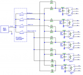
This transformer secondary winding wiring diagram is based on the info from post#12. You can see the output is always connect to RED wire, but the ground is not.
However, I can't figure out what is the impedance of each winding in order to achieve 2-4-8-16 ohm output. 🙁
One of the winding phase inverted for 8 ohm and 2 ohm?
Last edited:
Each winding segment is 1 Ohm, giving 4, 9, 16 when series or series parallel connected. All in parallel is 1 Ohm, called 2 Ohms since that might be useful (two 4 Ohm speakers in parallel).
It would seem that two DPDT switches would do to select 4, 8, 16 - but the specific order probably matters - the 8 Ohm connection shown (center pair in parallel) may be better than other combinations at high frequencies.
It would seem that two DPDT switches would do to select 4, 8, 16 - but the specific order probably matters - the 8 Ohm connection shown (center pair in parallel) may be better than other combinations at high frequencies.
- Home
- Amplifiers
- Tubes / Valves
- Advice on output Impedance selector switch