Dude, the more I play in Freecad, the more that I am awed by your work.
But I'm a total idiot when trying to create something in Freecad, much less with parametric constraints.
Could you make a offset driver TL with a S1 parallel, then S2 tapered?
The model really could be created best as a 2 segment TL

Here is the HR record:
ID = 54.10
Comment = 4 segment TL SBMW13TX - tapered w port-14L--F3-40Hz-good
|RADIATION, SOURCE AND MOUTH PARAMETER VALUES:
Ang = 2.0 x Pi
Eg = 10.83
Rg = 0.00
Fta = -3.99
|HORN PARAMETER VALUES:
S1 = 227.00
S2 = 227.00
Con = 35.60
F12 = 0.00
S2 = 227.00
S3 = 151.00
Con = 10.50
F23 = 0.00
S3 = 151.00
S4 = 50.00
Con = 39.50
F34 = 0.00
S4 = 50.00
S5 = 23.00
Con = 18.40
F45 = 0.00
|TRADITIONAL DRIVER PARAMETER VALUES:
Sd = 70.00
Bl = 5.76
Cms = 2.12E-03
Rms = 0.38
Mmd = 7.13
Le = 0.18
Re = 6.00
OD = 1
|ADVANCED DRIVER PARAMETER VALUES FOR SEMI-INDUCTANCE MODEL:
Re' = 0.00
Leb = 0.00
Le = 0.00
Ke = 0.00
Rss = 0.00
|ADVANCED DRIVER PARAMETER VALUES FOR FREQUENCY-DEPENDENT DAMPING MODEL:
Rms = 0.00
Ams = 0.00
|PASSIVE RADIATOR PARAMETER VALUE:
Added Mass = 0.00
|CHAMBER PARAMETER VALUES:
Vrc = 0.00
Lrc = 0.00
Fr = 0.00
Tal = 0.00
Vtc = 0.00
Atc = 0.00
Acoustic Path Length = 0.0
|MAXIMUM SPL PARAMETER VALUES:
Pamp = 100
Vamp = 25
Iamp = 4
Pmax = 40
Xmax = 5.8
Maximum SPL Setting = 3
|ABSORBENT FILLING MATERIAL PARAMETER VALUES:
Fr1 = 226.80
Fr2 = 218.40
Fr3 = 0.00
Fr4 = 0.00
Tal1 = 100
Tal2 = 100
Tal3 = 100
Tal4 = 100
|ACTIVE BAND PASS FILTER PARAMETER VALUES:
High Pass Frequency = 0
High Pass Slope = 1
Low Pass Frequency = 0
Low Pass Slope = 1
Butterworth High Pass Order = 1
Butterworth Low Pass Order = 1
Linkwitz-Riley High Pass Order = 2
Linkwitz-Riley Low Pass Order = 2
Bessel High Pass Order = 1
Bessel Low Pass Order = 1
2nd Order High Pass Q = 0.5
2nd Order Low Pass Q = 0.5
4th Order High Pass Q = 0.5
4th Order Low Pass Q = 0.5
Active Filter Alignment = 1
Active Filter On / Off Switch = 1
|PASSIVE FILTER PARAMETER VALUES:
Series / Parallel 1 = S
Series / Parallel 2 = S
Series / Parallel 3 = S
Series / Parallel 4 = S
|EQUALISER FILTER PARAMETER VALUES:
Band 1 Frequency = 0
Band 1 Q Factor = 0.01
Band 1 Gain = 0.0
Band 1 Type = -1
Band 2 Frequency = 0
Band 2 Q Factor = 0.01
Band 2 Gain = 0.0
Band 2 Type = -1
Band 3 Frequency = 0
Band 3 Q Factor = 0.01
Band 3 Gain = 0.0
Band 3 Type = -1
Band 4 Frequency = 0
Band 4 Q Factor = 0.01
Band 4 Gain = 0.0
Band 4 Type = -1
Band 5 Frequency = 0
Band 5 Q Factor = 0.01
Band 5 Gain = 0.0
Band 5 Type = -1
Band 6 Frequency = 0
Band 6 Q Factor = 0.01
Band 6 Gain = 0.0
Band 6 Type = -1
|STATUS FLAGS:
Auto Path Flag = 0
Lossy Inductance Model Flag = 0
Semi-Inductance Model Flag = 0
Damping Model Flag = 0
Closed Mouth Flag = 0
Continuous Flag = 1
|OTHER SETTINGS:
Filter Type Index = 0
Filter Input Index = 0
Filter Output Index = 0
Filter Type = 1
MEH Configuration = 0
ME Amplifer Polarity Value = 1
But I'm a total idiot when trying to create something in Freecad, much less with parametric constraints.
Could you make a offset driver TL with a S1 parallel, then S2 tapered?
The model really could be created best as a 2 segment TL
Here is the HR record:
ID = 54.10
Comment = 4 segment TL SBMW13TX - tapered w port-14L--F3-40Hz-good
|RADIATION, SOURCE AND MOUTH PARAMETER VALUES:
Ang = 2.0 x Pi
Eg = 10.83
Rg = 0.00
Fta = -3.99
|HORN PARAMETER VALUES:
S1 = 227.00
S2 = 227.00
Con = 35.60
F12 = 0.00
S2 = 227.00
S3 = 151.00
Con = 10.50
F23 = 0.00
S3 = 151.00
S4 = 50.00
Con = 39.50
F34 = 0.00
S4 = 50.00
S5 = 23.00
Con = 18.40
F45 = 0.00
|TRADITIONAL DRIVER PARAMETER VALUES:
Sd = 70.00
Bl = 5.76
Cms = 2.12E-03
Rms = 0.38
Mmd = 7.13
Le = 0.18
Re = 6.00
OD = 1
|ADVANCED DRIVER PARAMETER VALUES FOR SEMI-INDUCTANCE MODEL:
Re' = 0.00
Leb = 0.00
Le = 0.00
Ke = 0.00
Rss = 0.00
|ADVANCED DRIVER PARAMETER VALUES FOR FREQUENCY-DEPENDENT DAMPING MODEL:
Rms = 0.00
Ams = 0.00
|PASSIVE RADIATOR PARAMETER VALUE:
Added Mass = 0.00
|CHAMBER PARAMETER VALUES:
Vrc = 0.00
Lrc = 0.00
Fr = 0.00
Tal = 0.00
Vtc = 0.00
Atc = 0.00
Acoustic Path Length = 0.0
|MAXIMUM SPL PARAMETER VALUES:
Pamp = 100
Vamp = 25
Iamp = 4
Pmax = 40
Xmax = 5.8
Maximum SPL Setting = 3
|ABSORBENT FILLING MATERIAL PARAMETER VALUES:
Fr1 = 226.80
Fr2 = 218.40
Fr3 = 0.00
Fr4 = 0.00
Tal1 = 100
Tal2 = 100
Tal3 = 100
Tal4 = 100
|ACTIVE BAND PASS FILTER PARAMETER VALUES:
High Pass Frequency = 0
High Pass Slope = 1
Low Pass Frequency = 0
Low Pass Slope = 1
Butterworth High Pass Order = 1
Butterworth Low Pass Order = 1
Linkwitz-Riley High Pass Order = 2
Linkwitz-Riley Low Pass Order = 2
Bessel High Pass Order = 1
Bessel Low Pass Order = 1
2nd Order High Pass Q = 0.5
2nd Order Low Pass Q = 0.5
4th Order High Pass Q = 0.5
4th Order Low Pass Q = 0.5
Active Filter Alignment = 1
Active Filter On / Off Switch = 1
|PASSIVE FILTER PARAMETER VALUES:
Series / Parallel 1 = S
Series / Parallel 2 = S
Series / Parallel 3 = S
Series / Parallel 4 = S
|EQUALISER FILTER PARAMETER VALUES:
Band 1 Frequency = 0
Band 1 Q Factor = 0.01
Band 1 Gain = 0.0
Band 1 Type = -1
Band 2 Frequency = 0
Band 2 Q Factor = 0.01
Band 2 Gain = 0.0
Band 2 Type = -1
Band 3 Frequency = 0
Band 3 Q Factor = 0.01
Band 3 Gain = 0.0
Band 3 Type = -1
Band 4 Frequency = 0
Band 4 Q Factor = 0.01
Band 4 Gain = 0.0
Band 4 Type = -1
Band 5 Frequency = 0
Band 5 Q Factor = 0.01
Band 5 Gain = 0.0
Band 5 Type = -1
Band 6 Frequency = 0
Band 6 Q Factor = 0.01
Band 6 Gain = 0.0
Band 6 Type = -1
|STATUS FLAGS:
Auto Path Flag = 0
Lossy Inductance Model Flag = 0
Semi-Inductance Model Flag = 0
Damping Model Flag = 0
Closed Mouth Flag = 0
Continuous Flag = 1
|OTHER SETTINGS:
Filter Type Index = 0
Filter Input Index = 0
Filter Output Index = 0
Filter Type = 1
MEH Configuration = 0
ME Amplifer Polarity Value = 1
Attachments
Could you make a offset driver TL with a S1 parallel, then S2 tapered?
Hello joetekubi,
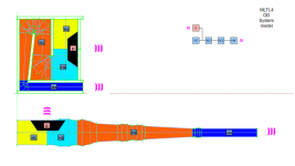
The model MLTL4 was already created for you, did you tried to simulate it? what was the issues you found while optimizing this particular design?
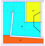
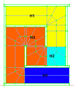
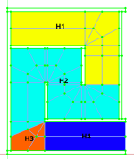
The MLTL4 has the segments H1, H2 and H4 with constant CSA and only H3 is flared, see attachment #1.
https://freeloudspeakerplan.rf.gd/pages/mltl4.htm
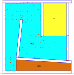
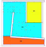
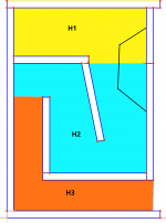
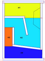
It would be easy to create a new model based on MLTL4, lowering driver position and so combining the intermediate segments into a single one and add flare in the last segment, see the attachments #2 and #3. H2 and H3 can be set to have the same flare so it will act as one single big segment but I like to offer more freedom when possible, so user could set different flare if it helps.
But before creating a new model I would ask you to share the results with current model MLTL4 and also to check if you can achieve desired result with current aspect ratio. I mean, once the layout is more or less the same and considering you already adjusted the model to achieve the desired total length for the "pipe" you could check if increasing L12 to lower driver position (increase D value) and combined H2 and H3 segments will delivery you a good result.
Sometimes playing around with Hornresp you achieve such a good results that might not be feasible in a real loudspeaker layout. I desired shape might be possible to achieved but the length of each segments may not and vice versa.
Attachments
Thanks Marcelo -
For the current project, I am trying to fit a TL into a ~14L desktop box, and have found two HR designs that appear to give me the F3 I want with a relatively short total line length. The designs for #1 and #2 above are close to what I need, as well as MLTL #4 if I delete segment H4.
I will play with MLTL #4 some more without H4 and it will probably work. Here is what my conception is looking like:

I can probably use MLTL #4 to accomplish this.
Another HR design is a constant taper. I should be able to accomplish this by altering MLTL #3 and deleting segment H3.
Once again, thanks so much for your great work. I'm sure I will have more questions later....

For the current project, I am trying to fit a TL into a ~14L desktop box, and have found two HR designs that appear to give me the F3 I want with a relatively short total line length. The designs for #1 and #2 above are close to what I need, as well as MLTL #4 if I delete segment H4.
I will play with MLTL #4 some more without H4 and it will probably work. Here is what my conception is looking like:
I can probably use MLTL #4 to accomplish this.
Another HR design is a constant taper. I should be able to accomplish this by altering MLTL #3 and deleting segment H3.
Once again, thanks so much for your great work. I'm sure I will have more questions later....
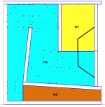
The schematic pictures I posted offer exactly the layout you suggest in the image #1, I'm reposting them with the driver indication to better ilustration. See attachment #1 and #2. But if you need longer L12 for H1 segment, the attachment #3 and #4 might be an alternative layout considering that some segments must have have constant CSA. The segment H1 can be flared if needed.
Your 3rd picture can be achieved with MLTL1 or MLTL3 if we modify the H3 segment to be flared other then deleting it.
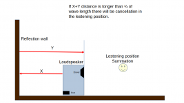
Note: Currently I'm not able to elaborate a Hornresp model with driver and vent/pipe/line pointing to different directions, that probably can cause cancellations due to wall reflection and I think Hornresp is not able to proper model them because the distance to the wall became important. I would suggest you to consider the vent/pipe/line always pointing the same direction as the driver.
Your 3rd picture can be achieved with MLTL1 or MLTL3 if we modify the H3 segment to be flared other then deleting it.
Note: Currently I'm not able to elaborate a Hornresp model with driver and vent/pipe/line pointing to different directions, that probably can cause cancellations due to wall reflection and I think Hornresp is not able to proper model them because the distance to the wall became important. I would suggest you to consider the vent/pipe/line always pointing the same direction as the driver.
Attachments
I've done ported boxes in the front and in the back. Not sure that I heard any difference!
The usual answer for port position is that the main frequencies coming out of the port are so long, that it doesn't make a real difference when summing with the wavefront from the driver.
In any case, this is a very minor consideration for me. First, fold the TL!
Thanks again.
The usual answer for port position is that the main frequencies coming out of the port are so long, that it doesn't make a real difference when summing with the wavefront from the driver.
In any case, this is a very minor consideration for me. First, fold the TL!
Thanks again.
In any case, this is a very minor consideration for me
Sure, and you know what you are doing so you can explorer more options for your use case, but once the models I share is for all public I think is important to highlight that issue because some user might not be aware about the cancellation phenomena.
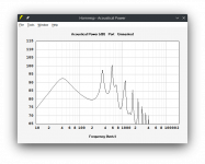
Let' register an example taking the attachment#1 as reference and lets calculate the 1/4 wave length for 40Hz reproduction in the port:
343/40/4 = 2,14m
But the port doesn't reproduce a fixed frequency, it's in fact a curve profile, see attachment#2, so other frequencies with shorter wave length are more affected.
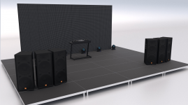
While this distance isn't probably an issue for home/desktop use because the loudspeaker might be positioned very close to the wall (a table might have 0,6m), in a PA use like a DJ stage it's clear an issue see attachment#3.
Once we finished this remark, let see what you bring as simulation results
Attachments
I am 100% in agreement with you concerning PA sound reinforcement design. All output must be forward. But for home use, you will usually be near a back wall, so much of the rear port output will be reflected and some cancellation may occur depending on distance from the wall.
Genelec rear wall bass effects
For my current design, HR "path" set to 11cm, equivalent to port on the front produces this power sim:

But setting "path" to 44cm, roughly equivalent to back top of box shows sim:

Once again, good talking with you. For me, I like to have choices. For home use, I'm pretty sure it doesn't make much difference for TL exits. Despite the HR port simulation, I don't think much midrange comes out a TL exit compared to the usual bass reflex port. I'll have to measure port frequency response sometime.
Genelec rear wall bass effects
For my current design, HR "path" set to 11cm, equivalent to port on the front produces this power sim:
But setting "path" to 44cm, roughly equivalent to back top of box shows sim:
Once again, good talking with you. For me, I like to have choices. For home use, I'm pretty sure it doesn't make much difference for TL exits. Despite the HR port simulation, I don't think much midrange comes out a TL exit compared to the usual bass reflex port. I'll have to measure port frequency response sometime.
Once again, good talking with you. For me, I like to have choices
Me too, I like talking. Choices and perseverance are one the key to succeed in any project. Keep gonging and lets complete your TL puzzle.

I've finally got some time to check some of these models out, and I'm running into some issues.
The model I'm trying to use is the TL2 model. It looks like it's not allowing me to set the value for "depth". Whatever I set it to, it keeps changing the value back to 574 mm.
Another thing is that you really don't need all those input values for the TL2 model. The only values you really need are:
1. Box Depth, D
2. Box Width, W
3. Box Height, H
4. Panel thickness, p (assuming same thickness for each panel)
5. Cutout diameter, D
6. Driver offset, o
7. Baffle offset, b
8. S1/S3 ratio, r
Everything else (panel dimensions, etc). can be calculated from those given values.
For example, the height of the vent @S3 (labeled as L2 in your image) is given by:
S3h = D/((1+1+r)+4*p+b)
Then the height of the vent @s1 (labeled as L2 in your image) is given by:
S1h = S3h*r
I forgot, this is the box I'm trying to reproduce as a FreeCAD model:

...and it's for this competition...
...and it's for this competition...
And the funny thing is that they messed up the BPH design too. It was said to be half of a Wicked One, but it certainly is not. Had they done it as a true half of a Wicked One, the performance should have been even better at low frequencies.
Not really. After running the specs of the enclosures through Hornresp, they seem Ok, but some of the performance claims seem to be overblown. It was some time ago, and I lost interest.
I've finally got some time to check some of these models out, and I'm running into some issues.
The model I'm trying to use is the TL2 model. It looks like it's not allowing me to set the value for "depth". Whatever I set it to, it keeps changing the value back to 574 mm.
Another thing is that you really don't need all those input values for the TL2 model. The only values you really need are:
1. Box Depth, D
2. Box Width, W
3. Box Height, H
4. Panel thickness, p (assuming same thickness for each panel)
5. Cutout diameter, D
6. Driver offset, o
7. Baffle offset, b
8. S1/S3 ratio, r
Hello Brain,
The reason for the issue you are facing is because depth is not an input for this model. This quote is blue colored and it means information for FreeCAD sketch. In the Tutorial section check the video How2use 3 and there you find more answers.
I do agree with you and in fact this model has only 8 input as you can see below:
Sketch inputs
1. thickness
2. baffle
3. D
4. L1
5. L2
6. faceoffset
Spreadsheet
7. cab int width
8. baffle hole
It could be reduced to 7 if we make L1 and L2 equals, but this would reduced the freedom to optimize this model.
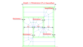
One of the advantages of CAD is that you don't need too many equations, to help you determine the depth you can consider the equations below:
depth = 4 * thickness + 3 * L1 + faceoffset
See attached illustration.
Attachments
I forgot, this is the box I'm trying to reproduce as a FreeCAD model:
There are some small differences between FreeCAD model and Boxplan one like:
FreeCAD consider the same CSA for H1 and H2 segment and the H3 make the CSA transition H4 (reduced CSA)
Boxplan consider the CSA transision at H2 and so your driver placement must be fixed at the beginning of the fold.
Attach you can find the T/S parameter I found for Peerless by Tymphany TC6FC00-04, Hornresp input .*txt file and also the 3D model I adjusted for you considering the external dimensions as you posted but internal ones are as closest as possible but not exactly the same due to model differences. Let me know if this is enough for you, otherwise I can customize it for you to precisely replicate your model.
External dimensions:
Height = 19,8cm
depth = 12cm
Width = 6,5cm
Total volume = 1,54L
Attachments
Below you can find an illustration regarding the FreeCAD and Boxplan model difference I mentioned in the post #137.
Boxplan:
S1 = 20.2 cm^2
S2 = 20.2 cm^2
S3 = 18.4 cm^2
S4 = 18.4 cm^2
S5 = 18.4 cm^2
L12 = 18.4 cm
L23 = 2.9 cm
L34 = 25.4 cm
L45 = 8.4 cm
FreeCAD:
S1 = 19.0 cm^2
S2 = 19.0 cm^2
S3 = 19.0 cm^2
S4 = 18.4 cm^2
S5 = 18.4 cm^2
L12 = 18.9 cm (This can be set up to 18.4 but looks like I mistype it)
L23 = 26.8 cm
L34 = 2.0 cm
L45 = 8.3 cm
Note: The same external dimensions and wood thickness were considered.
Attachments
[snip] The reason for the issue you are facing is because depth is not an input for this model. [/snip]
One of the advantages of CAD is that you don't need too many equations, to help you determine the depth you can consider the equations below:
depth = 4 * thickness + 3 * L1 + faceoffset
See attached illustration.
Ah, that explains it. I used to take a similar approach with my BOXPLAN models, until I realised that it was much easier for the user to enter the desired external dimensions of the box (e.g. if they're design for a specific size or space), rather than having one of the external dimensions being dependent on their choice of vent our mouth height, etc.
Not quite. BOXPLAN puts S2 at the driver's location, but it also allows the driver to be offset along the first fold (see image). S3 is used to make the end of the second fold. L34 is used for the transition around the corner to S4, and then L45 represents the rest of the path to the mouth.There are some small differences between FreeCAD model and Boxplan one like:
FreeCAD consider the same CSA for H1 and H2 segment and the H3 make the CSA transition H4 (reduced CSA)
Boxplan consider the CSA transision at H2 and so your driver placement must be fixed at the beginning of the fold.
- Home
- Loudspeakers
- Subwoofers
- Find here Parametric CAD files for loudspeakers plan - Hornresp integrated