Thank you, I will try first with 3.3 and then up as needed.
I was trying to understand your reference to the Zobel effect:
Pete: Doesn't this mean we have a 4.1 ohm resistor in series with a 3.3 uF capacitor, forming a Zobel network across the tweeter?
How do you get to 4.1 ohm in series? I can see 4.10 Ohm in parallel...
My apologies for the question, but why a resistance is added to a circuit, in both series and parallel rather than only in series or in parallel?
I also found the specs of my tweeter:
DC Resistance - Re - 5,2 Ohm
Voice coil Inductance - Le 0.1mH
Alex
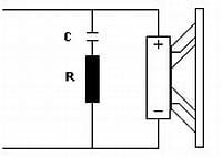
I am talking about the two 8.2 ohm resistors in parallel, which gives a total resistance of 4.1 ohm.
That 4.1 ohms is then in series with the 3.3 uF capacitor in the Zobel network.
The Zobel network is then in parallel with the tweeter (see attachment).
That 4.1 ohms is then in series with the 3.3 uF capacitor in the Zobel network.
The Zobel network is then in parallel with the tweeter (see attachment).
Attachments
Last edited:
My apologies for the question, but why a resistance is added to a circuit, in both series and parallel rather than only in series or in parallel?
The functions are quite different. The series 1.8 ohm resistor is for attenuation purposes, while the 4.1 ohm resistance is part of a Zobel network (an RC network) used to shape the response of the tweeter.
I also found the specs of my tweeter:
DC Resistance - Re - 5,2 Ohm
A DC resistance of 5.2 ohm is in accord with a nominal impedance of 8 ohm.
Galu, re:'Pete: Doesn't this mean we have a 4.1 ohm resistor in series with a 3.3 uF capacitor, forming a Zobel network across the tweeter?" - yep, I didn't look at the schematic, & try to avoid Zobels, I find them usually to be unnecessary with a 2nd order or higher xover. Here, however, we don't have an impedance plot of the tweeter to make the call.
My point about using the calculator still stands, as your example shows.
My point about using the calculator still stands, as your example shows.
My point about using the calculator still stands, as your example shows.
Yes, Pete - I quickly edited out my original comment about the calculator.

Hi All,
My initial enthusiasm to have found the right value to reduce the volume of my tweeter was... well, say just the excitement to have cut the treble without killing my ears.
So I went on with the listening, playing vinyl records, CDs , different genre of music, different resistors values, and came to the conclusion that 2.7 Ohm was the right value.
However, I am now experiencing another issue: the sound is 'sibilant' on the voices, to a level that I cannot stand it, and it generates fatigue to the listening.
I wonder if it depends on the quality of the resistor or perhaps its wattage is too low??
So let me summarize, so that you do not have to read the whole thread:
Could this issue be caused by the too low wattage of the current 2.7 Ohm resistor (5W)?
The wattage of the previous 1.8 Ohm resistor was 7W, so probably not, but I am asking, just in case. Regardless, I will go for at least 10W with the next one, that should not harm.
Otherwise, could the quality of the resistor itself be the issue?
As always, many thanks for sharing your thoughts.
.jpg")
My initial enthusiasm to have found the right value to reduce the volume of my tweeter was... well, say just the excitement to have cut the treble without killing my ears.
So I went on with the listening, playing vinyl records, CDs , different genre of music, different resistors values, and came to the conclusion that 2.7 Ohm was the right value.
However, I am now experiencing another issue: the sound is 'sibilant' on the voices, to a level that I cannot stand it, and it generates fatigue to the listening.
I wonder if it depends on the quality of the resistor or perhaps its wattage is too low??
So let me summarize, so that you do not have to read the whole thread:
- In the schematic below, where you see 1.8 Ohm, there is now a 2.7 Ohm resistor - this one
- My tweeter specs are below:
Nominal Power: 10W
Music Power: 120 watt
Frequency Response: 2 ÷ 20 KHz
Sensitivity: (2.83V/m): 92 dB
Resonant frequency: 1200 Hz
Nominal Impedance: 8 ohm
- My power amp output is 450W/Channel into any load: 2,4,8 Ohm
Could this issue be caused by the too low wattage of the current 2.7 Ohm resistor (5W)?
The wattage of the previous 1.8 Ohm resistor was 7W, so probably not, but I am asking, just in case. Regardless, I will go for at least 10W with the next one, that should not harm.
Otherwise, could the quality of the resistor itself be the issue?
As always, many thanks for sharing your thoughts.
Sibilance is a challenge to reduce compared to your previous level problem. It could be showing you're getting closer. It will be difficult to guess what is the problem, the blend near the cross, the level, the tilt toward higher frequencies, the directivity or diffraction. I wouldn't worry about the type of resistor as you do. Find the sibilance first.
Yes, the resistor quality or wattage is not the issue - the 2.7 ohm, 5 W ceramic resistor you have chosen is just fine.
Sibilance is said to sit at around 5 kHz to 8 kHz.
Perhaps the reduced treble level could now be exposing an over exuberant upper midrange reproduction?
AllenB mentions possible causes that, unfortunately, you may not have the practical wherewithal to explore.
Sibilance is said to sit at around 5 kHz to 8 kHz.
Perhaps the reduced treble level could now be exposing an over exuberant upper midrange reproduction?
AllenB mentions possible causes that, unfortunately, you may not have the practical wherewithal to explore.
I hate to say it, but recently I had a sibilance issue with a MOX resistor. I know it was this resistor as changing back to a sandcast/ceramic one fixed the issue. My thought, use a different sandcast resistor, and forget the Mundorf MOX.
Thank you for your feedback.
I will try the easiest fist, for the moment.
@wolf_teeth: could you please point me to the resistor you have used to fix your sibilance problem?
At least I have an idea to start with.
Thank you!
I will try the easiest fist, for the moment.
@wolf_teeth: could you please point me to the resistor you have used to fix your sibilance problem?
At least I have an idea to start with.
Thank you!
To be honest, it was a no name 7W 1 ohm resistor VS the 1 ohm Lynk MOX. I'll see if the resistor has any more info on it, but I doubt it.
The final resistor/capacitor can have more to do with the tilt, the capacitor/inductor set can have more to do with the blend and the first resistor can have more to do with the level.. however they also interact.AllenB mentions possible causes that, unfortunately, you may not have the practical wherewithal to explore.
Don't be so quick to assume it's the resistor, until you find out whether the response was changed. Some issues can be fixed with just an equaliser or a change of component values.could you please point me to the resistor you have used to fix your sibilance problem?
That worked fine.
However, since then many things changed in my gear, I also moved to a new home and I have a much bigger room.
As a result, I find the need to apply a further cut to the high frequencies.
Since your speakers worked fine in your old room, perhaps you should be considering the acoustic environment of your new room.
Or could there have been an unsympathetic change of gear? 🤔
I agree. I was mainly stating that the Mundorf resistor was likely not the answer the OP was looking for, and could actually make it worse.The final resistor/capacitor can have more to do with the tilt, the capacitor/inductor set can have more to do with the blend and the first resistor can have more to do with the level.. however they also interact.
Don't be so quick to assume it's the resistor, until you find out whether the response was changed. Some issues can be fixed with just an equaliser or a change of component values.
With the 1.8 Ohm resistor, the volume of the high frequencies was simply too much, the rest was balanced.
The room has nothing to do with this, as I was already in this room.
With the 3.9 Ohm, the issue was not there, but at the end the sound was muffled.
If it is a question to find the right balance, then I think I should go for the L-Pad.
It is a lot of work every time to change the resistor. The entire xover is made up of three different PC boards, and I have to remove this one (this is an image with the old 1.8 Ohm resistor), therefore disconnect all the wiring and re-connect everything in the cabinet, is a pain in the neck.
Maybe, I should try an l-pad as previously suggested. Perhaps, two, one for the mids as well. At that point it should be easier to find the balance.
In the image, the top part is the Tweeter, the bottom is the Midrange, the other two PC boards are respectively for the top and bottom woofers.

I am pretty sure it is a question to find the right value, but that could be anything between 2.2 up to 2.6, and I have no instruments to measure the response, but I do have my ears. 😉
The room has nothing to do with this, as I was already in this room.
With the 3.9 Ohm, the issue was not there, but at the end the sound was muffled.
If it is a question to find the right balance, then I think I should go for the L-Pad.
It is a lot of work every time to change the resistor. The entire xover is made up of three different PC boards, and I have to remove this one (this is an image with the old 1.8 Ohm resistor), therefore disconnect all the wiring and re-connect everything in the cabinet, is a pain in the neck.
Maybe, I should try an l-pad as previously suggested. Perhaps, two, one for the mids as well. At that point it should be easier to find the balance.
In the image, the top part is the Tweeter, the bottom is the Midrange, the other two PC boards are respectively for the top and bottom woofers.
I am pretty sure it is a question to find the right value, but that could be anything between 2.2 up to 2.6, and I have no instruments to measure the response, but I do have my ears. 😉
I'm not sure variable L pads will solve your problem, but if you decide to go ahead it begs the question, how best to incorporate them in the circuit?
I would be inclined to omit the fixed attenuating resistor in both the tweeter and midrange circuit (the 1.8 ohm and 2.2 ohm in the above photo), as they would no longer be required. Replace or simply bypass each with a wire link.
I would also be inclined to remove the Zobel RC network that is in parallel with the tweeter since the L pad presents a constant impedance to the crossover network. You could simply lift one leg of the 3.3 uF capacitor off the circuit board to disable the Zobel.
Then simply add on the variable L pads as shown in the attachment.
Lets see what the expert, AllenB, thinks of my amateur ramblings! 🙂
EDIT: Note that your tweeter and midrange must be connected to the L pad with reversed polarity.
Attachments
Last edited:
- Home
- Loudspeakers
- Multi-Way
- How to further cut the high frequencies of my speakers?