Anytime you add resistance in series it increases the driver's effective Qts' and since tweeters are typically already high Qt it can in theory become under damped enough to increase sibilance in the 6-8 kHz BW depending on the XO point/slope.

So, GM, do you think that removing the series resistors and using variable L pads instead is a good idea?
At a glance seems reasonable, but XOs are not my forte other than 1st order, so just 'tossed out' a piece of otherwise well known physics as a possibility and WRT shelving, in my time that's what a pot was for with a bypass cap if wanting to let through some extreme top end. (AKA CD horn EQ) 😉.
AllenB agrees with frequency tilt.
I'm trying to determine the best way for Alex to incorporate the L pad into the tweeter circuit - before the Zobel, after the Zobel or no Zobel at all?
I'm trying to determine the best way for Alex to incorporate the L pad into the tweeter circuit - before the Zobel, after the Zobel or no Zobel at all?
Another option would be to use the original crossover that came with the company who designed the speakers.
At the time, (26 years ago) I purchased the components at a shop that was specialized in audio components (Internet was at the earliest dawn in our homes 🙄), so they offered me to design a better crossover for my speakers.
They came up with the schematics in my post #1. They said it would have been a better match for the music I was listening to: hard rock - as the sound would have been more dynamic and fuller.
The original crossover is still in its box:


Honestly, I do not even remember if I ever tried this one, but the good thing is that I have all its specs. (in Italian) but you will understand them: 😉

At least, I do not have to change anything on this one, but I expect a totally different sound coming out from my speakers, who knows. 🙄
Alex
At the time, (26 years ago) I purchased the components at a shop that was specialized in audio components (Internet was at the earliest dawn in our homes 🙄), so they offered me to design a better crossover for my speakers.
They came up with the schematics in my post #1. They said it would have been a better match for the music I was listening to: hard rock - as the sound would have been more dynamic and fuller.
The original crossover is still in its box:
Honestly, I do not even remember if I ever tried this one, but the good thing is that I have all its specs. (in Italian) but you will understand them: 😉
At least, I do not have to change anything on this one, but I expect a totally different sound coming out from my speakers, who knows. 🙄
Alex
So, you have the crossovers that were originally supplied for the speaker project, but which were never used.
Fire them on in there and tell us how they sound!
Fire them on in there and tell us how they sound!
Taking a closer look, the NT 830 board does not include the additional 'response shaping' components for the woofer pair, i.e., the components outside the shaded box on the schematic.
You are absolutely right, in fact, in the original project they state that the default crossover was the NT830 to be completed with the supplemental missing network (woofers).
So I need to create a separated PCB and connect it with the NT 830.
What would be the easiest and proper way to do this?
Alex
So I need to create a separated PCB and connect it with the NT 830.
What would be the easiest and proper way to do this?
Alex
You don't really need a PCB.
The single 100 uF capacitor could be hard wired straight across the terminals of the low bass (basso) woofer.
The contour network of parallel resistors, inductor and capacitors could be attached to a plywood base and hard wired together, then wired in series with the upper bass (alto) woofer. You can drill holes in the plywood to accept plastic cable ties that can hold the heavy inductor down securely.
Last edited:
Hi folks,
I downloaded a software to create the schematics, there are many to choose from, I tried KiCad 7.0.
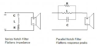
I studied how it works and started to draw the schematic of the 'parallel notch filter' you see in my post #67.

Also, I checked how to create the PCB, but there are too many parameters for my level of knowledge, so I wonder:
Alex
I downloaded a software to create the schematics, there are many to choose from, I tried KiCad 7.0.
I studied how it works and started to draw the schematic of the 'parallel notch filter' you see in my post #67.
- Could you please tell me if the drawing is correct?
Also, I checked how to create the PCB, but there are too many parameters for my level of knowledge, so I wonder:
- What would be the first course of action from here?
- I am aware this is a simple schematic, but I have no time to create the PCB myself, any recommendation on some online service that can take the above schematic and build the PCB?
- I can buy the parts separately and solder them myself, that is not a problem.
Alex
Last edited:
Your drawing looks correct, Alex. Well done handling the software!
I'll say again that this arrangement of components is so simple it does not require a PCB.
The physical components in a loudspeaker crossover need only be within 10% of the theoretical value, except in very critical applications.
Therefore, you could substitute a single 220 uF capacitor for the two paralleled 100 uF capacitors (equivalent to 200 uF).
Similarly, a single 2.2 ohm resistor could replace the two paralleled 4.7 ohm resistors (equivalent to 2.35 ohm).
These substitutions would greatly simplify the process of hard wiring I described in post #71 - give it a rethink.
An alternative is to look for a Crossover Development Board.
https://www.hificollective.co.uk/article/loudspeaker-accessories/crossover-pcbs.html
https://www.hificollective.co.uk/article/loudspeaker-accessories/crossover-pcbs.html
Hi Galu,Your drawing looks correct, Alex. Well done handling the software!
I'll say again that this arrangement of components is so simple it does not require a PCB.
The physical components in a loudspeaker crossover need only be within 10% of the theoretical value, except in very critical applications.
Therefore, you could substitute a single 220 uF capacitor for the two paralleled 100 uF capacitors (equivalent to 200 uF).
Similarly, a single 2.2 ohm resistor could replace the two paralleled 4.7 ohm resistors (equivalent to 2.35 ohm).
These substitutions would greatly simplify the process of hard wiring I described in post #71 - give it a rethink.
What you state is true, but I wonder why the original manufacturer did not simplify that way in the first place, there must be a reason why they have preferred individual components.
Also, about the inductor required of 5mH, my current crossover has one of 5.6mH, very high quality, you can see the details here , I am pretty sure I have seen somewhere a formula to reduce the number of windings to take it down to 5mH, but cannot find it right now.
Would that be a reliable method to measure its Ohm resistance with my digital tester?
Since I am not satisfied with my current crossover, there is no point I do not use some of the existing old components, in particular that 'Corobar' inductor, I'd save good money by using them.
Alex
- Home
- Loudspeakers
- Multi-Way
- How to further cut the high frequencies of my speakers?