Or just buy 10 of the 3.9, you can combine them in anything from less than 1 to 39.
The fix when you have what you want.
Jan
The fix when you have what you want.
Jan
I often tilt or roll down tweeters. Sometimes I use inductors to do this. I don't see an inherent problem with this but maybe I'm missing something... So somewhere I heard the inductance of a typical wirewound resistor as used in a crossover has 7nH, or was it 7μH of parasitic inductance? Even 7μH alone wouldn't attenuate 8 ohms by 0.1dB until 25kHz.Look for noninductive resistors,

Why not l-pad? Its variable, you can adjust highs to any level, instead of testing various resistor values and swapping.
https://www.parts-express.com/L-Pad-100W-Mono-1-Shaft-8-Ohm-260-265
https://www.parts-express.com/L-Pad-100W-Mono-1-Shaft-8-Ohm-260-265
I've been using the same set of variable L pads on my lounge speakers for over 30 years and have had no problems with reliability.
re:'downsides to using an l-pad" - they are usually only used for an initial setup, then left in a single position. Over time, the rest of the element becomes oxidised and sounds scratchy when the wiper is moved. A pair of fixed resistors eliminates this problem, and is cheaper.
My 30+ year old L pads are not "scratchy" - perhaps it depends on where you live - humidity levels etc.
Perhaps importantly, I rotate the wipers fully from time to time to ensure they and the resistance wire tracks remain clean.
Perhaps importantly, I rotate the wipers fully from time to time to ensure they and the resistance wire tracks remain clean.
There can be differences in response between L-pads and series resistors because the impedance seen by the crossover can be different in each case. But the location of the series resistor vs. L-pad, amount of attenuation, driver impedance, inclusion of impedance equalizers, etc. also influence this, so it's hard to generalize.Are there downsides to using an l-pad, other than the installation?
I have nothing against the L pads but I guess I would need to drill a hole on the back of the speaker, like right above or below the banana connectors.
Also, 8 Ohms would be fine, as the tweeter is 8 Ohms.
I guess no additional changes should be done to the current Xover, right? Essentially, the two resistors in the L-pad do the trick.
When it comes to choose the right L-Pad, any specific brand is recommended? I guess there are multiple levels of quality on the market??
Or are we just looking at standard stuff, as it is just a knob with two resistors? 🙄
You're thinking of a variable L-pad. Quality isn't a concern for sound.. maybe for mechanical feel and durability. Consider power handling as always.
Yes, if you add a variable L pad control you need make no additional changes to the crossover circuit.
Rather than drill holes in your lovely enclosures, you may like to reconsider increasing the value of the 1.8 ohm resistor (to 3.9 ohm in the first instance). This is a simple and easily reversible solution to your problem.
P.S. All currently available L pad controls probably originate from the same factory. The one linked to by adason is typical of what is available. They do, however, come in different power ratings. I can obtain 8 ohm L pads in 100, 50 and 15 W versions.
I'll attach a link later that will allow you to view the available options.
Here are the L pad options available to me: https://willys-hifi.com/collections/l-pad-attenuators
The 50 W version looks neat!

The 50 W version looks neat!
You could just use a switch to switch between two sets of Lpads, 'normal' and 'high cut.' Do you know what tweeters those are and whether they are ferro-fluid cooled type?
If you're worried about having enough power from the amp, and want to liberate your bass performance, you should use an active xo on just the bass. You probably have a suitable extra amp sitting around!
If you're worried about having enough power from the amp, and want to liberate your bass performance, you should use an active xo on just the bass. You probably have a suitable extra amp sitting around!
Yes, you can increase the value of the resistor in the 1.8 ohm position.
Try standard values from 2.2 ohms and upwards (2.7, 3.3, 3.9, 4.7 etc.).
I would add when it comes to fine tunning at the end, you may need to listen to two different values with 0.5 ohms difference only. This can be reached by // two resistors to get a more precise value than the standard standalone solded ones.
Rotary L-Pad is the way to go to find easily the good values you need at the end... or you can keep the L-Pad on the loudspeaker if of a good quality enough for your daily use.
Hi guys,
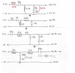
Today I have removed the Tweeter + Midrange PCB from my right speaker, and I have realized that the change suggested and applied to reduce the hi frequencies, was as per image below.
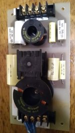
I also took a picture of the PCB.
So, since I should receive the resistors today from DigiKey, as a first step, I would replace the 1.8 Ω in series with the 2.2 Ω and see how that sounds.
I am asking because before we based our conversation on the fact that only the resistor in series was changed, but in reality also the one in parallel was changed.
Thoughts?
Alex
Today I have removed the Tweeter + Midrange PCB from my right speaker, and I have realized that the change suggested and applied to reduce the hi frequencies, was as per image below.
I also took a picture of the PCB.
So, since I should receive the resistors today from DigiKey, as a first step, I would replace the 1.8 Ω in series with the 2.2 Ω and see how that sounds.
I am asking because before we based our conversation on the fact that only the resistor in series was changed, but in reality also the one in parallel was changed.
Thoughts?
Alex
Attachments
If you use the calculator linked in post #4, you can see the effect of changes, which should help you understand what's happening. Use the DC Resistance of your tweeter in the 'Speaker Impedance' field.
So, the OP has edited his attachment in his introductory post to now show that an additional 8.2 ohm resistor was added in parallel with the original 8.2 ohm resistor.
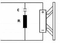
Pete: Doesn't this mean we have a 4.1 ohm resistor in series with a 3.3 uF capacitor, forming a Zobel network across the tweeter?
Alex: I read that the function of the Zobel network is to "sweeten the top end" of the tweeter.
Pete: Doesn't this mean we have a 4.1 ohm resistor in series with a 3.3 uF capacitor, forming a Zobel network across the tweeter?
Alex: I read that the function of the Zobel network is to "sweeten the top end" of the tweeter.
Attachments
Last edited:
Alex, I would ignore the 8.2 ohm scenario for now and simply go ahead with increasing the value of the 1.8 ohm resistor.
I would try 3.3 or 3.9 ohm initially.
I would try 3.3 or 3.9 ohm initially.
According to Pete's calculator, the 1.8 ohm resistor is currently providing just under 2 dB of attenuation.
Increasing to 2.2 ohm would take it just over 2 dB, whereas 3.3 ohm would give 3 dB.
You'll likely have to go higher than 3.3 ohm to get an audible difference in tweeter level.
4.7 ohm would give 4 dB of attenuation.
Increasing to 2.2 ohm would take it just over 2 dB, whereas 3.3 ohm would give 3 dB.
You'll likely have to go higher than 3.3 ohm to get an audible difference in tweeter level.
4.7 ohm would give 4 dB of attenuation.
- Home
- Loudspeakers
- Multi-Way
- How to further cut the high frequencies of my speakers?