Its all a bit strange and I've no answers or suggestions without knowing more about what this noise looks like.
One thought... if it is both channels and if it is a 'buzz' which could be mains frequency related (and the scope will show that) then could it be riplle injection into the amp caused by running it at a higher bias current than the original transistors were run at.
The more current you draw from the supply the more the ripple increases. The amp should be relatively immune to noise on the rails but is it?
so here is the final cenario, and i will use the scope later, but you may have to help me determine what the noise may be
switch to 8 ohms
if i have both channels at around 45mv across the 1 ohm i get no noise, increase the left further and it starts to buzz
put the left back to 45 and increase the right it doesnt buzz
put the left on 0v and increase the right above 25mv and it does not buzz
so it only buzzes when both channels have voltage across the 1 ohm above 45mv
the original output across the 1 0hm setting was max 30mvIts all a bit strange and I've no answers or suggestions without knowing more about what this noise looks like.
One thought... if it is both channels and if it is a 'buzz' which could be mains frequency related (and the scope will show that) then could it be riplle injection into the amp caused by running it at a higher bias current than the original transistors were run at.
The more current you draw from the supply the more the ripple increases. The amp should be relatively immune to noise on the rails but is it?
measuring across the 1 ohm, the adjustment was very stable untill you got to about 45mv, then it suddenly jumps to 80,or 250, or even 400+mv.
Has the sudden jump in voltage resolved with going driverless? Sudden jumps suggest a problem.
if i have both channels at around 45mv across the 1 ohm i get no noise, increase the left further and it starts to buzz
put the left back to 45 and increase the right it doesnt buzz
So no noise at 45mv for both

Left buzzes at higher current
Right channel does not buzz no matter what current you set
put the left on 0v and increase the right above 25mv and it does not buzz
Again, all good with the right channel
so it only buzzes when both channels have voltage across the 1 ohm above 45mv
This is the one I don't get 🙂
Does the left channel buzz seem ti be dependent on the right channel current? or is it only the left channel that buzzes when you have more than 45mv for the left channel?
Scope... we need to see what this noise is.
No-so it only buzzes when both at at or above 45mv, so in other words they dont buzz individualy if you reduce the current to zero on each, then measure the other
its a shame they dont do videos on here i would show you what i mean
its a shame they dont do videos on here i would show you what i mean
'Has the sudden jump in voltage resolved with going driverless? Sudden jumps suggest a problem'-yes this has been resolved
'Right channel does not buzz no matter what current you set'-you can increase either channel to what ever you like if the opposite channel is at zero
'Right channel does not buzz no matter what current you set'-you can increase either channel to what ever you like if the opposite channel is at zero
so with both channels set at 50mv there is no buzz,and it is def a value thing because i tried it
I put a fixed resistor in one side equal to 175mv and one in the other side at 25mv and it buzzes
reduce the 175 down to 75mv, leave the other at 25mv and the buzz goes away so 100mv combined or over causes the buzz
I put a fixed resistor in one side equal to 175mv and one in the other side at 25mv and it buzzes
reduce the 175 down to 75mv, leave the other at 25mv and the buzz goes away so 100mv combined or over causes the buzz
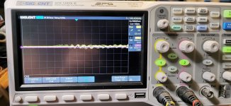
ok so here we go with the scope
pic 1 is
left channel set at 100mv
right channel set at 0mv
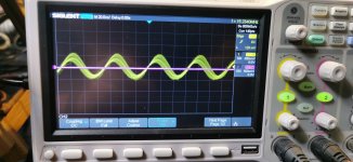
pic 2 is
left channel set at 100mv
right channel set at 45mv
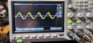
pic 3 is
left channel set at 100mv
right channel set at 100mv
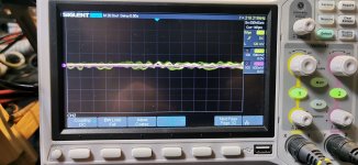
pic 4 is
left channel set at 0mv
right channel set at 100mv
do you see what i mean about the combined voltages
there is def noise on the left channel even when it is turned right down, but it isnt audible untill you reach the thresholds of around 50mv on each channel
could it be that we are just going above component original thresholds
pic 1 is
left channel set at 100mv
right channel set at 0mv
pic 2 is
left channel set at 100mv
right channel set at 45mv
pic 3 is
left channel set at 100mv
right channel set at 100mv
pic 4 is
left channel set at 0mv
right channel set at 100mv
do you see what i mean about the combined voltages
there is def noise on the left channel even when it is turned right down, but it isnt audible untill you reach the thresholds of around 50mv on each channel
could it be that we are just going above component original thresholds
Attachments
reg supply temp didnt turn out to be an issueso i have exactly 100mv across each 1 ohm now, increase increments are smooth and no noise now at all
my only concern is the regulated supply transistors are quite warm, more than normal at 40c,so we will have to see how this goes once i apply a load and they may need to be upgraded
Can I poke in this folie à deux ?
I'm no expert in any way but are you sure it's not related with the Power Envelope sagging with the power demand ?
Just and idea.
I'm no expert in any way but are you sure it's not related with the Power Envelope sagging with the power demand ?
Just and idea.

Don't think so.could the presets themselves be the issue
I'll look at the scope images later 🙂 but they look to show something really high frequency going off the F= readout at the top right of the screen.
Quick thought... the soft clip circuit uses reference voltages common to both channels. What happens if you remove these:
Aye 🙂Can I poke in this folie à deux ?
I think this noise is appearing with no audio present. It can be heard when just setting the bias current.
The output inductor is there to isolate the output stage from any unintended capacitive loading (such as the self capacitance of some speaker cables) which can cause oscillation and instability.
The thing with your noise is that you describe it as buzz which means low frequency, perhaps a few tens or hundred Hz but no higher.
Your scope shots don't seem to show anything like that. What you really need to do is set the timebase to a slower speed such as 5 or 10 milliseconds per division and see what this buzz looks like at that sort of speed.
Try removing those caps I circled to see if the soft clip is feeding anything rail related into the amp. Keep using the bulb for safety though.
The soft clip switch only alters voltage thresholds. There is always a connection from rails to amp input so removing those caps would eliminate that from our enquiries 🙂
We never tried any of this with the other amp as we set it at 27mv and never went any higher,so I guess we will never know with that one. The amp worked realy well at that setting, so 45 or 50mv would be more than enough with this amp. Maybe the initial design just won't Warrent the current we are looking for. I might do another 3020 FET mod and see if you get the same issues as they are basically very simlar
- Home
- Amplifiers
- Solid State
- NAD 3130 conversion to Lateral FET