I've eventually got a choke input supply up and working. SIC 1200V Wolfspeed diodes. FT-3 teflon 0.1uF first cap. Big potted 8H choke rated 210mA. Followed by a 12uF DC Link cap.I have not used a vacuum tube rectifier since about 1996. I use some HEXFRED diodes, and plan on using more.
Slightly expensive, but less than a quality vacuum tube rectifier, and they will never fail in my amplifiers. I think that overall performance is best with Choke Input B+ filters. Most of my amplifiers have less than 100uV of hum and noise at the 8 Ohm load.
It's good! Clean and clear with good tone. Audibly better than the same SS setup with a 4uF first cap. So I can see that when it comes to a SS supply, choke input is the way to go. It's different from the same setup with a 5U4 rectifier. Cleaner, a bit less warm and full. Not sure yet which I would prefer but this is a contender - needs more work and more listening.
But this is early days - it's under voltage by about 30V, hums a bit, and I have to add more capacitance and another choke, to make it LCLC. It's a pain re-planning the mains transformer(s) but looks like it's worth it. If I go on to use a 5U4 with choke input it would need a lot more AC voltage.
Last edited:
SS diodes, especially the fast ones, have hard cutoff at their forward voltage. This causes ringing of transformer resonant tank, with frequency spectrum up to RF. Snubbing reduces ringing, but doesn't completely eliminate it. Snubbing is only effective at the ringing fundamental, but not at harmonics.
Slower diodes are better in this respect. The difference between fast and slow diodes is the same as difference between striking a bell with a steel hammer and felt-tipped stick. Fast diodes were designed for high frequency switching, they have no advantage whatsoever at line frequency.
Vacuum tube rectifiers, completely free of this fault, are my only choice.
Last edited:
The best tube rectifiers are damper diodes. Very slow start, high current capability, low voltage drop. 5U4 is voltage-waster.

I don't think you need to use an expensive Teflon for the 0.1 cap, Id save that one for audio coupling someday. A Sprague Orange Drop would be a good type there.
Snubbing is only effective at the ringing fundamental, but not at harmonics.
Can you elaborate on this? I'm confused. If you dampen the fundamental with snubbers will the harmonics not follow as well?
We can look at it in time domain. Switching spike starts multitude of decaying sine waves. Snubbing reduces only one frequency.
1. Is anybody using a Tektronix P5100 1500V high voltage probe to look at all that ringing?
Or another similar capability probe?
Did you properly compensate that probe on your scope?
Please send us some screen shots of the power transformer's secondary ringing (that I am hearing about in this thread).
That would be much appreciated.
A proper picture is worth 1,000 posts that talk about the ringing.
And, be sure to do it using:
No 0.1uF input cap, No snubbers, and be sure to use some HEXFRED diodes or SIC diodes instead of a vacuum tube rectifier.
Oh, be sure to use AC coupling so that you can increase the scope V/div to see exactly how small that ringing is.
Caution: the P5100 divides the voltage by 100 Before it reaches your scope's 300VDC or 600VDC AC blocking capacitor.
That is the only correct way to protect your scopes front end.
A lesser probe will blow out your scopes AC coupled front end.
And, do not forget to have good grounding, and No ground loop between the scope and the amplifier.
How do you check for that? Well . . .
Connect both the scope probe tip, and the scope probe ground clip, . . . to the ground point of the amplifier's B+ circuit.
Do not be surprised if you see a signal there . . . ground loops are in more places than you can imagine.
Measurements are both an art and a science.
2. A 0.1uF capacitor is 15,900 Ohms at 100Hz of a full wave rectified 50Hz power main.
I guess you can "call that a choke input filter".
50mA Load, 100Hz, 0.1uF would have 795V peak to peak ripple. That should qualify 0.1 uF as not being a cap input filter.
Last edited:
Damper diodes do indeed have their fans but I could never get good results from them, and I tried 6BY5G and 6DT4 in a few builds. I preferred the 5U4. And again, I prefer the 5U4 to the GZ34 which has less voltage drop. Not sure why exactly but that's what I found.The best tube rectifiers are damper diodes. Very slow start, high current capability, low voltage drop. 5U4 is voltage-waster.
As for FT-3 teflon 0.1uF I have loads of them, and they were very cheap at the time I bought them so I might as well use them. No idea if anyone could tell the difference against a metallised polypropylene one, probably not. We don't have many Orange Drops in the UK.
I used the method shown at the M. Johnson thread linked at post #14.Please send us some screen shots of the power transformer's secondary ringing (that I am hearing about in this thread).
That would be much appreciated.
A proper picture is worth 1,000 posts that talk about the ringing.
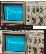
That is, short the unused windings and inject a fast square wave into the winding in question, then watching the CRO adjust R for best results.
Looked exactly as it does at the illustration in his thread, my example is below:
Attachments
thaiDiy,
Thanks for mentioning Post # 14, that had a screen shot of a special case circuit . . .
Unfortunately, it was not taken from a Working B+ circuit of a working amplifier that had:
HEXFRED or SIC diodes: a choke input B+ filter: and a real DC load on the B+.
You are putting a Square Wave into your transformer.
I hope your local Power Mains company does not put square waves into your house.
Nice, but these are 2 different cigars.
(Horses of a different color).
Is there a problem with ringing in a hybrid or Graetz bridge?
I ask because I use a 5U4 without a centre tap and with a couple of SIC 1200V diodes.
I ask because I use a 5U4 without a centre tap and with a couple of SIC 1200V diodes.
The square wave is to simulate the switching of the rectifier and its effect on the power transformer secondary.You are putting a Square Wave into your transformer.
I hope your local Power Mains company does not put square waves into your house.
Somewhere buried in M. Johnsons thread he offers 100 UK pounds to anyone who can find a difference between the simulation and real-world practice using the same transformer, same R+C//C across the secondary, driving the rectifier of a DC power supply. You could always look into that further, I just took it at face value.
Are you by chance modelling this using PSUD2 or Spice? I found PSUD2 essential when improving and designing a couple of my amps. You may uncover a specific reason that you prefer the 5U4 instead of other rectifiers for your given circuits.Damper diodes do indeed have their fans but I could never get good results from them, and I tried 6BY5G and 6DT4 in a few builds. I preferred the 5U4. And again, I prefer the 5U4 to the GZ34 which has less voltage drop. Not sure why exactly but that's what I found.
As for FT-3 teflon 0.1uF I have loads of them, and they were very cheap at the time I bought them so I might as well use them. No idea if anyone could tell the difference against a metallised polypropylene one, probably not. We don't have many Orange Drops in the UK.
Although I'm not convinced that M. Johnson's goal of critical damping is needed for power supply secondaries, his Quasimodo bell ringer should be very handy in adjusting damping for output transformer primaries (and even loaded secondaries). Currently no DIYers are bothering, but it's the new hot thing for Golden Ears.
For power transformer secondaries, Johnson's method of C//RC does all that needs doing: the large C swamps the smaller variable C of semi-con junctions passing between on and off, and the RC damps the di/dt. HV (high vacuum) diodes don't have significantly variable C (which would cause some RF wiggle) and their C is very small, so they don't couple much forward into the B+, for whatever that's worth.
The RC snubber, or Zobel, damps a two pole resonant circuit, 40dB/decade falloff above resonance, so it could be said that it doesn't have a special effect far above resonance. Johnson's parallel larger C reduces the resonant frequency, so shifts the whole rolloff slope to the left (towards lower frequencies). Every decade shifted left is 40dB reduction at any particular frequency above resonance.
I don't think there's really any good reason to strain for critical damping; very overdamped works just as well at the penalty of heating up the damping R a little more.
All good fortune,
Chris
5Y3 ia limited to 125mA, the 5Y3 is 250mA if my load current are close to those limits, i will use SS rects...
now tv dampers have higher currents but is only half wave, so you need two at least....
now tv dampers have higher currents but is only half wave, so you need two at least....
Elvee showed nice screenshots on PY88 damper and a few SS diodes in Valve rectifier with high frequency AC #33.I used the method shown at the M. Johnson thread linked at post #14.
As for mitigating the hum. The first thing I'd do is size L1 properly. To install a 250ma input choke in a PS that will never have to supply over 80ma of current is missing a great opportunity to get more inductance. Lets say the circuit draws 80ma of current, so go select an 80 ma choke with the most henries you can find. Even if the demand goes to 85-90 ma that 80ma choke will only derate its henries a smaller percentage. It sounds to me like 250ma is way oversized for your real draw, what is that number? What is your expected draw for this PS? With choke input its best to be over minimum inductance if you can with L1 which means size it with inductance priority over ma derating priority. If heat becomes an issue then increase the choke ma side just a little to still keep the inductance as high as you can.
Last edited:
Thanks Windcrest. I have 3 big chokes in 3 different and separate chassis. My PSUs are on separate chassis. Two are 8H at 210mA potted, one is 10H at somewhere around 200mA, not potted. I could juggle the chassis around but I don't want to rebuild the 2 functioning 5U4 chassis. The SS supply has a 8H choke. But it supplies 2x 2a3 output tubes at 60mA each, so total is 120mA. For choke input I would expect to use these 3 chokes. I have smaller Hammond chokes which I can use for L2 in a variety of values. That should help the hum.
The capacitors I intend using are
I'm finding it hard to choose between the 5U4 supply and the SS choke input one. The 5U4 is smoother and more resonant and has a looser sound with more bass. The choke input SS is tighter, thinner in tone, faster, more percussive, more definition and clarity in complex textures, but less bass, though tighter, and more of an upper midrange emphasis. This clearly needs more work but it has potential. My wife calls the 5U4 "warm and in the room" and the SS "like being in the Albert Hall". That's pretty accurate. We like both in different ways, but they are different.
I still haven't got PSUD working on my Mac - must try and load that.
Update: Just tried a second 5U4 PSU and it's better. Very similar to the other 5U4 supply but cleaner - maybe a better layout, plus a similar but different choke. Starting to go more with the 5U4 supply but more to come.....
The capacitors I intend using are
- Russian KBG-MN copper foil PIO in either 1uF or 4uF, 600V. I have a few so could parallel some. These are the best caps
- Kemet DC Link caps. I suspect these roll off the high frequencies but I don't know why, more noticeable as the value increases. Otherwise they have good tone, better than electrolytics which I also have as Kemet 550V, 86uF.
I'm finding it hard to choose between the 5U4 supply and the SS choke input one. The 5U4 is smoother and more resonant and has a looser sound with more bass. The choke input SS is tighter, thinner in tone, faster, more percussive, more definition and clarity in complex textures, but less bass, though tighter, and more of an upper midrange emphasis. This clearly needs more work but it has potential. My wife calls the 5U4 "warm and in the room" and the SS "like being in the Albert Hall". That's pretty accurate. We like both in different ways, but they are different.
I still haven't got PSUD working on my Mac - must try and load that.
Update: Just tried a second 5U4 PSU and it's better. Very similar to the other 5U4 supply but cleaner - maybe a better layout, plus a similar but different choke. Starting to go more with the 5U4 supply but more to come.....
Last edited:
Hammond 159P, 193G, 193GP all fall in that current range, but all are 10H, so it looks like 10H is the most inductance you can get in an off the shelf choke at this current. So none of these beat the 10H 200ma you, have so thats a good choke, no opportunity here to squeeze in a couple henries based on mfg catalog. I thought they'd make a 13H or so at 120ma but they don't. Your wife and mine would get along good, she now looks forward to going to Axpona with me each year.
- Home
- Amplifiers
- Tubes / Valves
- Solid state versus tube rectifiers in a PSU