Driving a transistor to immediate failure and using it for long term reliability are two different things.
And any industry would use safety factors, only how safe is safe.
I certainly would not want my electronics to fail.
My speakers are too expensive, and I am not as rich as Nelson. 😉
Patrick
And any industry would use safety factors, only how safe is safe.
I certainly would not want my electronics to fail.
My speakers are too expensive, and I am not as rich as Nelson. 😉
Patrick
Hello Patrick,
you are right. There should always be a safety margin...
Have a nice weekend
Dirk
you are right. There should always be a safety margin...
Have a nice weekend
Dirk
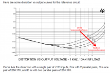
I was delighted to see the attached figure, in Nelson's technical paper about this circuit. It's one of those thrilling situations (to me anyway) in which academic theory and practical reality agree beautifully. Just exactly as James Solomon predicted in 1974. diyAudio member @Bonsai kindly makes Solomon's tutorial available online, here .
In a different thread, Nelson had this to say:
In a different thread, Nelson had this to say:
_... The J113 as an example has lower transconductance than the K170 Jfet types, and so will have less capacity for processing feedback. ... This issue can be addressed by using different quantities of them in parallel and degenerated, but it's a pain in the butt. Easier to spend a little money on the K170s.
Attachments

Front end bias is 3mA total, according to post # 20.
That means 1.5mA per fet for the LTP.
Yfs at 1.5mA for 2SK170 is ~ 17mS.
Yfs at 0.75mA for 2SK209GR is ~ 8mS.
So I would definitely invest in a bunch of 2SK209GR (~30USD for 100 pieces) to get 2 quads, before I pay for a quad of 2SK170s.
Unless of course you already have the latter. 🤓
https://www.diyaudio.com/community/threads/njfets-for-source-follower-applications.329131/
Patrick
If you add a duplicate of R6 to the other drain leg of the diff/quad pair, I don't see an excursion problem with them being driven by ±32V. All of the other transistors not so, but there are other options there.
Slightly off-topic question - I've been thinking about a DIY integrated amp with an input/buffer stage and maybe an F4 or F5 output stage. Would this front match with an F4 or F5 - with a regulated PS for the front end the universal PS for the output?
The voltage on the drain(s) attached to R6 do not get below about 1 volt less than the V+ supply. Thus Vds(Q1) will be about 2 volt less than the V+ supply input. The variation of Vds will approximately 1/10 the variation of the output. As a result, Q1 and Q2 should not see a Vds above about 35V, assuming 32V supply to the FE.If you add a duplicate of R6 to the other drain leg of the diff/quad pair, I don't see an excursion problem with them being driven by ±32V. All of the other transistors not so, but there are other options there.
Well the F4 is a big power buffer "hot follower" with 0db of gain but lots of current drive capability. All of your voltage swing needs to come from the FE / preamp / gainstage whatever in front. The F5 has ~15db of gain. So, maybe a preamp with a gain of 2 is suitable for that one? It's important to figure out what kind of gain you really need for your own ears, room, listening habits, speakers, etc. when you're trying to connect all these "LEGOs for adults". And the amp / speaker interface matters. For example, certain amps just don't really excel with 4 ohm speakers. The FE presented here reminds me of the old original BA-1/BA-2 FE, another simple discrete op-amp. Similar but different. Complementary BA-2 output stage is just like the F4. But F4 has that little buffer up front that may or may not be needed depending of what people are hooking to these things. The single-ended BA-1 OS is really nice, lived with that one for awhile. There are pros and cons to all this stuff. So, the answer is very simple..... keep reading and learning, build everything, and enjoy the journey.... 🙂Slightly off-topic question - I've been thinking about a DIY integrated amp with an input/buffer stage and maybe an F4 or F5 output stage. Would this front match with an F4 or F5 - with a regulated PS for the front end the universal PS for the output?
True, but there would be a little more margin for signal excursions with another R and it wouldn't hurt.The voltage on the drain(s) attached to R6 do not get below about 1 volt less than the V+ supply. Thus Vds(Q1) will be about 2 volt less than the V+ supply input. The variation of Vds will approximately 1/10 the variation of the output. As a result, Q1 and Q2 should not see a Vds above about 35V, assuming 32V supply to the FE.
Putting a resistor on the drain(s) of Q2 would have little effect on the resulting voltages and distortion. Run the simulation.
I have changed R6 to 680 Ohm, as in the original schematic. I had to adjust R7 to 660 Ohm, to get a very low output-offset (below 1mV).
I measured only 1.2 V over the 660 Ohm resistor (R7) = circa 2mA over the JFets - hmmm 🤔
seems low for me? Sounds good.
In my first version I had R7 at 330 Ohm and R6 adjusted to circa 50 Ohm. In the measurement this was slightly 3rd harm.dist. dominant.
In my second version -with resistors as mentioned above- the measurement showed more 2nd harmonic distortion.
Only some of my experiences - I don't know if they have any value?
Cheers
Dirk
Attachments

Are you measuring correctly ? - i see Distortion very high even with R6 is as per schematics. What is the output Voltage when you measure the noise and distortion? Compare your numbers with the Pa' document.
Hello kannan_s,
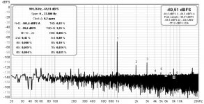
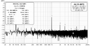
could be that anything is wrong with my measurements. I also saw the pretty high distortion.
Inputvoltage was 2 V sinus, at output 10kOhm resistor. Forgot to measure outputvoltage.
Greets
Dirk
could be that anything is wrong with my measurements. I also saw the pretty high distortion.
Inputvoltage was 2 V sinus, at output 10kOhm resistor. Forgot to measure outputvoltage.
Greets
Dirk
I am just guessing. The certain offset is needed to get the best performance.
R6 is 680, assuming 0.6V Vbe for Q5, the current thru R6 is 0.9mA. Mr.Pass mentioned slightly <3mA for the first stage. Q2 should have around 2mA. Thus there should be a positive offset at output.
If we do the FE in very traditional way, the current thru Q1 and Q2 should be roughly equal to minimize the offset.
That is why I tried to reduce the current of the first stage to <1.8mA.
But people with inside knowledge never said to minimize the offset to get the best performance.
So far we don't know the offset of the reference schematics. I wish 6L6 could give us some hints.
Since there is capacitor at output, do we really care to minimize the offset?
@6L6, @william2001- thanks for your replies. My speakers aren't really demanding 4 ohm loads - I use a pair of Zu and a pair of Linn Ninkas.
I don’t play very loud. The F4 seems to be a great sounding amplifier but requires some gain up front. I think the gain on the new front end is up to 10db?
Some amplifiers don’t need more than a pot to control volume - maybe the F5 is in the category. Also wonder is this front end with the F5 is too much rain overall for my use.
Thanks again - bmdduck
I am just guessing. The certain offset is needed to get the best performance.
R6 is 680, assuming 0.6V Vbe for Q5, the current thru R6 is 0.9mA. Mr.Pass mentioned slightly <3mA for the first stage. Q2 should have around 2mA. Thus there should be a positive offset at output.
If we do the FE in very traditional way, the current thru Q1 and Q2 should be roughly equal to minimize the offset.
That is why I tried to reduce the current of the first stage to <1.8mA.
But people with inside knowledge never said to minimize the offset to get the best performance.
So far we don't know the offset of the reference schematics. I wish 6L6 could give us some hints.
Since there is capacitor at output, do we really care to minimize the offset?
fact - some ppl are taking one Vbe as 600mV, some as 650mV, some as 700mV
ignoring that really depends of exact part and current trough, it is basic figure used as guide; tight guide, but not exact number carved in stone
That's what I'm talkin' about. I did run it and of course it has no detrimental effect, but many would say just build it. For me, all in good time...Putting a resistor on the drain(s) of Q2 would have little effect on the resulting voltages and distortion. Run the simulation.
My real point was that the J113s are not limiting the rails, except for the current sources, but those don't really need to be J113s.
- Home
- Amplifiers
- Pass Labs
- DIY Front End 2022