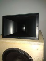
First arrived the horns.
Is it some kind of intervention that used between the horn and driver?
Is it some kind of intervention that used between the horn and driver?
Attachments
Last edited:
Thank you.The driver is screwed directly to the horn and has an integrated seal.
I haven't any driver on hand yet.
Reihelt split the order in 4 parcels 📦
I haven't received any up to now.
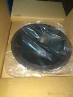
A horn driver arrived now.
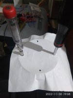
I find that I have two options to mount the driver with the horn ,either i will use the two only existing holes or i will use only one existing one and open three new holes. In the first case, the driver will be supported on only two diametrically opposed screws in the second case, the loudspeaker will rest on all 4 screws.
What is better?
Another question,do I need aluminium screws?
Attachments
Last edited:

Thanks for the answer.This is normal. Just use the two that fit.
Something new arrived at home.
Attachments
Because I can have it made with tagstrips on a piece of wood in about 1/2 the time it takes to design a PCB.I have a general question.
Why we don't prefer the pcb usage for crosover parts mounding?
Thanks but if it isn't any other disadvantage i can do it.😉Because I can have it made with tagstrips on a piece of wood in about 1/2 the time it takes to design a PCB.
I just don't see any practical advantage to a xover PCB except to speed up production, to make it easier (to some extent) for inexperienced constructors, or for the designer to make more money. Except if you wish to mount it externally as a display item a la PBN.
The printed circuit boards bring a very big disadvantage:
When soldering together, you have to turn the PCB over and always think mirror-inverted.
This is therefore a potential, very large source of error.
If you think the wrong way just once, the whole speaker will no longer work properly.
Then you are either disappointed with the result, because you are not aware of the error, or you have to go on an extensive troubleshooting.
Therefore, I advise against printed circuit boards, unless you know exactly what you are doing.
Thanks for answer,don't worry,i know exactly what i doing and i'm very-very careful too. 🙂The printed circuit boards bring a very big disadvantage:
When soldering together, you have to turn the PCB over and always think mirror-inverted.
This is therefore a potential, very large source of error.
If you think the wrong way just once, the whole speaker will no longer work properly.
Then you are either disappointed with the result, because you are not aware of the error, or you have to go on an extensive troubleshooting.
Therefore, I advise against printed circuit boards, unless you know exactly what you are doing.
I haven't decided which solution I will prefer.
Perhaps the solution without a pcb gives the opportunity for easy displacement of the components, as I know,placing the coils in a different rotation gives the advantage of avoiding interaction.Traces are shorter also.
Ηowever, the pcb solution looks neater and more professional. 🤔
Last edited:
Once it’s inside the box 🤷🏻♂️, i wouldn’t take a lot of time for thatThanks for answer,don't worry,i know exactly what i doing and i'm very-very careful too. 🙂
I haven't decided which solution I will prefer.
Perhaps the solution without a pcb gives the opportunity for easy displacement of the components, as I know,placing the coils in a different rotation gives the advantage of avoiding interaction.Traces are shorter also.
Ηowever, the pcb solution looks neater and more professional. 🤔
Am I completely satisfied? ............ Not quite. Would love to have a treble driver, which was a bit softer in it´s presentation. More like
the 4367, which to my ears doesn´t quite sound as agressive in the uppe octaves, as the Tymphany does.
I know, you tried a lot of different drivers for "Asathor", so if you have any suggestions, I´d love to have some, since I´m not at all
familiar with PA-stuff.
Look for drivers with a (HT) Polymer - the same as the JBL D2430K, or Mylar diaphragm.
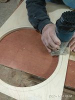
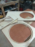
I have a question about the routerThe hard work.
My friend John is very helpful 😊
how precise is it by hand?
could you share close up pictures?
im trying to find the best solution for my own designs….
Do not even try it. Takes a very tallented carpenter with an extremely calm hand and years of experience to follow a line free hand with a router. Same with a jig saw. To cut a straight line or perfect circle looks much easyer than it is.
Most do it with a device that is fixed in the middle of the circle as pictured. You first cut the recessed parts and keep the center material until finished. Cut until you have a few milimeter left and then use a jig sam for the last bit.
If you got a router you should have one, as it is quite useless without it. You get them in different sizes or can build one your self with a router. Does not have to look perfect. A good project to learn how to use the router, too.
You can make circles twice the size of the tool. As you may use it for tweeter too, it is more interesting how small it can work, not how large.
Hint: Do not make the part where the router is fixed to strong, as you will loose depth for the router bit.
The one pictured is made especialy for this Makita tool, there are universal ones and plans for them in the net, too.
Last edited:
Not very precise,you need a better way.I have a question about the router
how precise is it by hand?
could you share close up pictures?
im trying to find the best solution for my own designs….
CNC is the right way but isn't available.🙁
Turbowatch2 way is fine but you need to do this at first,before you cut the circle hole.👍
I cut my first round speaker hole with a handmade jig 40ya. For the last 20 or so I've used the inexpensive Jasper Jig. Works perfectly fine. I've seen handmade jig how-tos on YT too, but didn't save links.CNC is the right way but isn't available.
CNC is nice, but NOT needed, even for odd shapes like waveguides or non round speaker drivers like 6MD38. Different technique required for the latter, but not difficult at all.
- Home
- Loudspeakers
- Multi-Way
- Asathor - a JBL 4367 Clone