Can't see the thiele small infoThat is chineese crap using the famous brand. But fortunately the production of hifi drivers is continued by a former employee who bought manufacturing equipment 25 years ago and is now using the name Great Plains Audio https://great-plains-audio.myshopify.com/products/515-8c-15-low-frequency-alnico-loudspeaker
Unfortunately the price were greatly increased after a recent takeover, quality and specs same as Altec
The 515 is one of the best sounding woofers ever made
U need to make some friends , I can run it obviously they put the admin pwd but even , can't play with it much,during normal office hrs.IT security.
Wish I worked at Twitter before musk.lol
You have a link in the bottom of the pageCan't see the thiele small info
working now.You have a link in the bottom of the page
hey 150 watts of power, (0.20" around 5mm Xmax ) and there is no BL rating.
for 1200 bucks ?
Are the any plans to use freecad in the reverse to hiw
Hello @laxandredeyed Could you elaborate more, what reverse to hiw means?
Amazing, thank you.
Hello 27ph,
Here is the Altec817 model using exponential horn as the original plan, but as you can see in the simulation comparison also attached, both gives basically the same result.
is up to you to choose the aesthetic you like more or witch one is easier to build.
Looks like for the previous model only one macro was updated and working correctly.
Attachments


It seems half my post didn't make it through. I wondered if there were any plans to be able to tweak a design in Hornresp, then use a macro to come up with a dimensioned drawing in FreecadHello @laxandredeyed Could you elaborate more, what reverse to hiw means?
It seems half my post didn't make it through. I wondered if there were any plans to be able to tweak a design in Hornresp, then use a macro to come up with a dimensioned drawing in Freecad
It wound be hard to do it, and it may generate some errors because while in a real box layout you have so many constrains in hornresp you have much more freedom, so, sometimes what you achieve in hornresp might not be possible in a real enclosure.
For instance, The cross sectional area in a horn is a two dimension interaction, like S (CSA) = A (height) x B (width), so when you increase the S inside hornresp he didn't know if you are changing A or B and for hornresp it doesn't matter but thinking in a real enclosure it matter a lot.
Some tips while reverse improvements from hornresp to CAD:
- If you need to increase all cross section at the same time, it's better to change only the box width. See Attachment #1
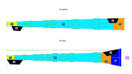
- If you need to change a particular CSA, it's better to change the height of duct size or increase the flare but it may affect also some sorrowing dimensions, sometime you also need a different layout. For example, you are simulating and Tapped Horn and you see on hornresp that increase S4 and S5 you can improve the response, but you are simulating the TH-MTH, you can not revert that because it has a single flare. If you change to TH-SS1 you can do it, because as you can see in the attachment #2 TH-SS1 has one more flare in the segment H3.
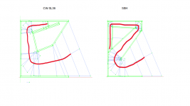
- When you need to increase or decrease a horn path you may need to change to a different layout because there is a range they work. See attachment #3, as you can see with SBH you can achieve long path length compared to the CW-SL36. You will see that even with FreeCAD you will try to reduce something but you achieve the bottom, so for instance, in a Tapped Horn the minimum path for each layout might be the minimum baffle you can accept to assembly the driver.
Above examples are to illustrate to the difficult behind reverting data from Hornresp to CAD. So accumulating experience the user can understanding those interactions and wisely choose the best design / layout.
The advantage of FreeCAD and the Macro come to play at this moment because it speed up a lot the process. You can also ask for help here in the forum 🙂
Attachments
Alright LORD, me and FreeCAD are not getting along. I thought there was a way to import HR txt files so I don't have to update the Excel fields. I go to update the Excel fields that say CM but you have to put in MM quantities. I tried change the wood thickness from 18mm to 19.05mm and the view blew up.
That happen to me alsoEither do ALL mm or ALL cm, not both.
Either do ALL mm or ALL cm, not both.
Hello BP1Fanatic and maxolini,
Behind the scenes FreeCAD work only with mm, but visually we can use whatever unit we want, so if you enter a value without unit indication it will be understand always as mm, if you type the value followed by units like =35cm so it will be understood as indicated, even inch can be used if it easier for you, like =35in
If you right click with mouse on a cell, proprieties, display units, you will see that I already setup them according to hornresp input. So a agree with you that it is strange because if you enter the value without unit it's undertood as mm but you see as cm. To avoid this confusion, you can enter the value followed with unit you are considering.
Example: You will see that Vrc uses l as units and Atc uses cm^3 both refer to volume, hornresp works in this way, so the idea was to make easier for the user to translate the data to hornresp without need to make conversion, FreeCAD convert for us.
Summary: What you enter as a value and and what you see can be different in terms of unit, but the unit conversions must be coherent. I hope it make more sense now and allow you to move on.
At the tips and tricks section in the website there is an indication about how you can change the global unit system, this will allow you to work with inches inside sketch if you prefer, but at the end, the hornresp inputs are already defined.

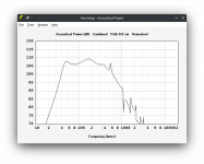
FYI/FWIW, etc., some Altec 515-16G factory horn cab response measurements.I found the attached plan for the Altec 817, is it OK to use it as reference with the JBL 2226 driver?
Attachments
![Altec 515-16G in [4] horn cabs_page3.jpg](/community/data/attachments/1043/1043439-e83f4c2cb3f10ff6c2275b1815b06acd.jpg?hash=6D9MLLPxD_)
Hi Mr LS -
As discussed in the Hornresp thread, I would like to build something like this.
Is there anything I can do that might help you build that version in your software?

As discussed in the Hornresp thread, I would like to build something like this.
Is there anything I can do that might help you build that version in your software?
- Home
- Loudspeakers
- Subwoofers
- Find here Parametric CAD files for loudspeakers plan - Hornresp integrated