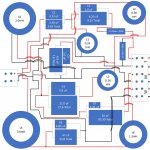
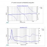
I'm new to DIY speakers, but I'm having fun and learning. I've learned enough to be dangerous, but that's enough to attempt a first build. I used a few different online tools to create the initial 3-way design and then messed around with xSim to refine it. I settled on a 3rd order passive and have what looks to me like a decent result. I know this can't be perfect as I've not modeled the crossover with respect to the enclosure. So a few questions - 1) I've attached the frequency and impedance curves and would like opinions on them. Is this a good result or should I continue to refine? 2) What's next? Should I build it and then test/refine some more? 3) Also attached is my board layout. The board 16" X 16" and all parts are to scale. I'm using Jantzen caps, Solen 14 AWG inductors, and plan to use 14 AWG solid core OCC copper to point to point wire the entire crossover. I know I could better optimize the wiring, but some of the way it's shown is to help me keep everything straight when I build it. Thanks in advance for your help.
Attachments
A couple quick suggestions:
1) Include a screen grab of your XSim model/schematic so the crossover is easier for others to analyze without a lot of energy. Personally, I'm too lazy to untangle a board layout for a quick look/chat. And hopefully the XSim model is laid out in a typical fashion, so the topology is obvious.
2) Many designs include a gradual downward tilt with increasing frequency to make the speaker more forgiving. You have a gradual upward tilt. If you like brighter/ruthlessly revealing speakers, that may be intentional. If not, it may need some mid/tweeter level adjustment.
In the end, the simulations only tell you so much, so I typically suggest early/ugly prototypes to see how you like what you have. If you're picky, the crossover will likely require adjustment by ear no matter what, so there's not much point in delaying that excessively.
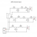
Thanks Matt. I've added the xSim schematic. I have an L-pad on the tweeter and can adjust it down a bit, but I thought I'd leave it the way it is until I listen. I can't hear above 10K, so I'm thinking a brighter speaker might be a good thing? Of course If I can't hear it, brightness will only serve to drive my wife crazy.
Any thoughts about the impedance curve? I tried a notch filter to eliminate the woofer resonance and was able to do it quite well, but it required a 85mH inductor with a 1650uF capacitor. I thought that was a bit much and since it's mostly below 30hz, figured it won't matter much.
Any thoughts about the impedance curve? I tried a notch filter to eliminate the woofer resonance and was able to do it quite well, but it required a 85mH inductor with a 1650uF capacitor. I thought that was a bit much and since it's mostly below 30hz, figured it won't matter much.
Attachments
Last edited by a moderator:
Yeah, I learned PDQ that women were needed to do HF 'anything' audio above the 16 kHz EQ point and as I got older, eventually above the 8 kHz point. 🙁 The downside is that they used whatever system 'we'/ I had more than I did WRT to 'critical/enjoyment' listening, though did give me that much more time indulging in other hobbies they had zero interest in, so win-win overall! 🙂

I don't see anything worrisome in the impedance plot. Woofer impedance around resonance is typically left natural. If you aren't running a tube amp with high output impedance or don't have some other specific reason to go after it, flattening impedance in that region tends to be impractical and of little benefit with today's typical amps.
If you place the speakers close to a wall, the upward tilt in frequency response might also be beneficial. Again, a lot of this comes down to personal preference and room conditions, so until you have a prototype up and running, some stuff is hard to predict.
If you place the speakers close to a wall, the upward tilt in frequency response might also be beneficial. Again, a lot of this comes down to personal preference and room conditions, so until you have a prototype up and running, some stuff is hard to predict.
Last edited:
Yep - my wife has dog ears. It's really amazing what she can hear that I can't. Same goes for smell, but that's more of a blessing!Yeah, I learned PDQ that women were needed to do HF 'anything' audio above the 16 kHz EQ point and as I got older, eventually above the 8 kHz point. 🙁 The downside is that they used whatever system 'we'/ I had more than I did WRT to 'critical/enjoyment' listening, though did give me that much more time indulging in other hobbies they had zero interest in, so win-win overall! 🙂
Makes sense. Thanks again for the input.I don't see anything worrisome in the impedance plot. Woofer impedance around resonance is typically left natural. If you aren't running a tube amp with high output impedance or don't have some other specific reason to go after it, flattening impedance in that region tends to be impractical and of little benefit with today's typical amps.
If you place the speakers close to a wall, the upward tilt in frequency response might also be beneficial. Again, a lot of this comes down to personal preference and room conditions, so until you have a prototype up and running, some stuff is hard to predict.
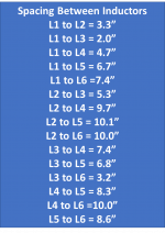
So I have another question - the inductors are all air cored spaced as far apart as I could get them. However, the space between L1 and L3 is only 2 inches. These are relatively small inductors being 0.24mH and 0.16mH, so 2 inches is probably okay. But to be sure, I can pull L6 off of this board and place it higher into the woofer cavity on it's own board. It would be at least 10 inches away from the woofer magnet and 10 or more inches away from the rest of the inductors. If I do that, I can reorganize the board and improve the distances for L1 to L3, which is only 3.3 inches. Am I milking cats or is this something I should do as 2 inches is really not sufficient (All my spaces are in the attached picture)?
Attachments
Just rotate the inductors.
However, the main problem is rising frequency response. This kind of speaker is going to sound bright and fatiguing in most rooms. Unless your listening space is very dead - or you firmly know you prefer bright sound - you better do the opposite, create slightly downward-sloping response. It would be easier to judge with tools that compute early reflections and sound power, like VituixCAD, but with simplistic one-dimensional simulators like xSim you better play it safe with response falling about 3 dB from 100 Hz to 10 kHz.
However, the main problem is rising frequency response. This kind of speaker is going to sound bright and fatiguing in most rooms. Unless your listening space is very dead - or you firmly know you prefer bright sound - you better do the opposite, create slightly downward-sloping response. It would be easier to judge with tools that compute early reflections and sound power, like VituixCAD, but with simplistic one-dimensional simulators like xSim you better play it safe with response falling about 3 dB from 100 Hz to 10 kHz.
Attachments
![7iyiem22gs1o[1].png](/community/data/attachments/1038/1038173-695b7de44aa7b4d3cb51f73c42a561cd.jpg?hash=aVt95EqntN)
I looked at rotating the inductors (Meaning putting on edge), but no matter which ones I rotate, there will always be a hole facing one of the other inductors. Based on that diagram, holes are problematic even at 3.9 inches away. I agree with the brightness thinking, but thought I'd leave it until I hear it. Or maybe I'll go with an adjustable L-pad rather than fixed resistors. Any experience with adjustable L-pads?Just rotate the inductors.
However, the main problem is rising frequency response. This kind of speaker is going to sound bright and fatiguing in most rooms. Unless your listening space is very dead - or you firmly know you prefer bright sound - you better do the opposite, create slightly downward-sloping response. It would be easier to judge with tools that compute early reflections and sound power, like VituixCAD, but with simplistic one-dimensional simulators like xSim you better play it safe with response falling about 3 dB from 100 Hz to 10 kHz.
Your board is big. L3-L5 distance is about 12 inches, L1-L4 is 9 or 10. I would not worry about it.

If using L-pads I would take a flat, horizontal curve as starting point and make +-3 dB pads.
Yamaha NS-1000M with L-pads in "neutral" position is similar to your initial curve. We used them in a few rooms - both as monitor and as home speaker - and the first thing to do was always turn the adjustments 3 dB down, producing flat response. Frankly saying, we barely touched the contlols again, and, certainly, never went for another 3 dB up 🙂
I just learned something new about MS PowerPoint. Even though I drew everything to scale and put it on a 16 x 16 square, PowerPoint does not scale properly on the diagonal. In my case, drawing a line from one corner to the opposite corner of a 16" square shows a dimension of 16". So all of my dimensions for L1 and L3 are incorrect. I guess that's new math?Your board is big. L3-L5 distance is about 12 inches, L1-L4 is 9 or 10. I would not worry about it.
View attachment 1130275
If using L-pads I would take a flat, horizontal curve as starting point and make +-3 dB pads.
Yamaha NS-1000M with L-pads in "neutral" position is similar to your initial curve. We used them in a few rooms - both as monitor and as home speaker - and the first thing to do was always turn the adjustments 3 dB down, producing flat response. Frankly saying, we barely touched the contlols again, and, certainly, never went for another 3 dB up 🙂
View attachment 1130280
I'll play around more with L-pads. I may need one on the midrange to flatten it out. I appreciate the input Thanks again.
You have not engaged the phase plot for each driver. While you're there, turn off system phase.
Have you included your baffle?
Have you included your baffle?
No, I've not included a baffle as I really have no idea how to do it. As for the phase plots, I'm not certain what you mean there either. In xSim, I see where I can add individual drivers to the frequency plot, is that what you mean?You have not engaged the phase plot for each driver. While you're there, turn off system phase.
Have you included your baffle?
I've not purchased drivers, so really anything is on the table. However, these 3 are what I'm currently focused on.Without knowing what the drivers are, it's impossible to say whether the xover is appropriate;
links to data sheets would be helpful
Attachments
I used to have SB15NRX (mk1) in an MTM - I think they sound average/below average and unless they made some miraculous upgrade, you can select something better for the mid.
https://www.diyaudio.com/community/threads/current-best-5-midrange-driver.378212/
https://www.diyaudio.com/community/threads/current-best-5-midrange-driver.378212/
Thanks for that feedback. Do you have a mid that you'd recommend? I originally wanted to use one of AudioTechnology's drivers, but couldn't find enough data to feel good about it.I used to have SB15NRX (mk1) in an MTM - I think they sound average/below average and unless they made some miraculous upgrade, you can select something better for the mid.
Depends on what cross points you plan, amongst other things. I would look instead at SS Illuminator or Revelator, e.g. 12MU dedicated mid. There's also the new Purifi. You also might be able to still source an NE149 somewhere. I'm sure AT is great but the price is....wow.
Anyway, if you've not bought anything, then download this Scanspeak Excel file from here
https://www.madisoundspeakerstore.com/calculators
Use SS datasheets to change the driver input values and enter a baffle width -- see what mounting broadly does to the frequency response of a 22W/25W/15W -- this is going to have a major impact on any XO for any similar diameter drivers.
Most people will say it's ambitious to build a good speaker and crossover your first time with a 3-way and to go instead with an established kit/published design for success and saving money otherwise from iterations and failures - just food for thought.
Last edited:
I hear you about this being ambitious for my first build, but I'm not too worried about it. If I buy a bunch of stuff, build it and it stinks, I'll just try again. If it still stinks causing me to give up, I'll sell all the stuff I bought on ebay and take the "L".Depends on what cross points you plan, amongst other things. I would look instead at SS Illuminator or Revelator, e.g. 12MU dedicated mid. There's also the new Purifi. You also might be able to still source an NE149 somewhere. I'm sure AT is great but the price is....wow.
Anyway, if you've not bought anything, then download this Scanspeak Excel file from here
https://www.madisoundspeakerstore.com/calculators
Use SS datasheets to change the driver input values and enter a baffle width -- see what mounting broadly does to the frequency response of a 22W/25W/15W -- this is going to have a major impact on any XO for any similar diameter drivers.
Most people will say it's ambitious to build a good speaker and crossover your first time with a 3-way and to go instead with an established kit/published design for success and saving money otherwise from iterations and failures - just food for thought.
Why I want to do my own rather than a kit is that I had an idea for a unique enclosure/baffle design that I've never seen before. Somebody probably tried it and found it stinks, but regardless, I want to build it and see for myself. The problem of course is that I know nothing about speaker/crossover design and even if the enclosure/baffle could work well, my inexperience with the crossover might ruin the SQ. To that end, I could just buy a pre-assembled XO, but I'm thinking that approach will pretty much guarantee poor SQ - plus I'm learning and having fun messing around with it.
- Home
- Loudspeakers
- Multi-Way
- Looking for opinions on my first passive crossover