Okay. Then, it sounds like you are starting toward the right direction with NOS. As you’ve no doubt noticed in this thread, however, there is more to implementing NOS than simply dispensing with any Digital Filter. For example, the DAC chip you choose will determine the requirements for the I/V circuit. In addition, you need to de-serialize/de-multiplex and format the incoming digital data stream - which is done by the Digital Filter chip when it’s present.It was some years ago when i built an Aikido preamp and a Nelson Pass F4 with help from the forum .. i was always lacking a standalone DAC so i decided that my audio chain suffers and among all other DIY projects i stumbled on this thread that i find more interesting .. i just want to build a decent NOS R2R DAC .. that's all .
Yes .. i suppose a JLSounds I2SoverUSB will be my input and for I/V stage i am still considering the options either for default OPA implementation or a custom solution like EUVL 's newest FC CEN IV with fixed rails .. thanks for your input ..Okay. Then, it sounds like you are starting toward the right direction with NOS. As you’ve no doubt noticed in this thread, however, there is more to implementing NOS than simply dispensing with any Digital Filter. For example, the DAC chip you choose will determine the requirements for the I/V circuit. In addition, you need to de-serialize/de-multiplex and format the incoming digital data stream - which is done by the Digital Filter chip when it’s present.
@NIXIE62 is giving it a shot with the same chip (albeit smd version) with a converter pcb on a pcm63p dac that @miro1360 designed. It's not finished yet, and the bunch of us that have finished, in his vicinity, are not plugging out our chips for the life of it 😀 So if you are inclined to wait a bit, he can tell you if it works/how it sounds.Yes i know who you talk about .. i sent him pm but he wouldn't ship to Greece where i live ..yes i avoid Chinese vendors.. i have found original PCM1702P in Europe that's why i want to try with this chip ... anyway thanks for your input ..

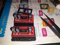
As soon as I get that famous PCM1702, we'll try it right away. The adapters are there, the small capacitors that go with the PCM1702 have been purchased.
That chip is famous, some claim it is among the best of all time. I'm curious to see how it will turn out in this assembly intended for PCM63.
among the hidded famous, then...
Let see how it turns. I know no chips that doesn't need (different surrounding layout) a bit of tweaking to voice them in relation to each others. It is already not easy just to switch an opa, but a dac chip even less on its analog output stage. Often the best dacs devices are the ones that have been a lot optimized (I mean the whole device)
Let see how it turns. I know no chips that doesn't need (different surrounding layout) a bit of tweaking to voice them in relation to each others. It is already not easy just to switch an opa, but a dac chip even less on its analog output stage. Often the best dacs devices are the ones that have been a lot optimized (I mean the whole device)
That "optimization" of yours is already in the domain of pure philosophy.
I will optimize just a pair of I/V resistors, because the PCM1702 has a lower Iout (+-1.2mA) than the PCM63 (+-2mA).
Everything else must be the same, in order to realistically evaluate the sound of those two chips. And that's all assuming it will work as a PCM63 replacement.
I will optimize just a pair of I/V resistors, because the PCM1702 has a lower Iout (+-1.2mA) than the PCM63 (+-2mA).
Everything else must be the same, in order to realistically evaluate the sound of those two chips. And that's all assuming it will work as a PCM63 replacement.
well it will give an idea indeed... I bet for a clearer sound on PCM1702... (than the pcm63)
philosphy... my dacs are So crate !
philosphy... my dacs are So crate !
Last edited:
A Philips CD582 relinquishes it's TDA1541A! Hopefully I didn't kill it removing!


Is this tda1387 thing directly swappable with the 1541?

Miro 1541 DAC, PSU and DC blocker boards on their way. Will have a small amount spare in the UK.
Is this tda1387 thing directly swappable with the 1541?
Miro 1541 DAC, PSU and DC blocker boards on their way. Will have a small amount spare in the UK.
Last edited:
Getting my pair of FC CEN I/V boards built, adjusted and mated to my AD1862 DAC took a bit longer than I anticipated with the holiday break. But, today we have music! All seems to be working smoothly so far. Patience has paid off with this project as my DC offset is stable and less than 1mV(both channels).
Thank you to Patrick for sharing your creation and build support, Fran your amazing build guide and Miro’s DAC platform.

Thank you to Patrick for sharing your creation and build support, Fran your amazing build guide and Miro’s DAC platform.
Attachments


Nice work as always Vunce. I'm still struggling with my FC CeN so have taken a step back from it!
What is your PSU for the IV?
What is your PSU for the IV?
I allow myself a bit of showing off. 🤓


LT3045 / 3094 you can get commercial ones.
Patrick
LT3045 / 3094 you can get commercial ones.
Patrick


I am considering to get a AK4113 input board with a display. Just to be sure:
- from this thread I grasp this board is compatible with the AD1862. Is that correct?
- the AK4113 can do up to 192 kHz, and is already somewhat older. Is there a more up to date alternative ready made input board available?
Please clean the tda1541A legs without eating too much.A Philips CD582 relinquishes it's TDA1541A! Hopefully I didn't kill it removing!
View attachment 1128156View attachment 1128155
Is this tda1387 thing directly swappable with the 1541?
View attachment 1128157
Miro 1541 DAC, PSU and DC blocker boards on their way. Will have a small amount spare in the UK.
And put it on a good socket adapter, it is ok, you have much more to worry about everything else with that chip than wanting to solder it again on a pcb (just in case it was the plan). Have desoldered dozen of TDA1541A, never had a problem : I use a good desoldering pump and zat solder sucker flat wire I forgot the english name. the secret is of course not to force on the heat and let cool teh substract between two legs work ! (and of course avoid electro static electricity)
I am considering to get a AK4113 input board with a display. Just to be sure:
- from this thread I grasp this board is compatible with the AD1862. Is that correct?
- the AK4113 can do up to 192 kHz, and is already somewhat older. Is there a more up to date alternative ready made input board available?
ok but you must know, spidf and Toshlink is a good sound limiter whatever the chip and interface. You really should consider usb board to I2S Xmos chip based. I really like te Wave I/0 with its non isolated side on uf-l pads outputs if your streamer is clean (noise I mean). Some of the Miro's ad1862 pcbs has uf-l inputs and I strongly advice to go with them. The JLSounds Lab is the choice if you use the ad1862 board you can stack with avoiding wires. And the isolation layout of the JLSounds is finely made.
the best Spidf ever made is imho the DIR901 something (NLA but can be found) ... never remember that exact ref, always mix it up with Porsche 911 ! Mind is strange.
Of course : R-Core traffo if you can, two, one for the digital, one for the analog, secondaries dedicated to each supply : input frontendboard, "digital" chip side (if that makes sense as they share the ground ref) and analog output. I found the fire & forget PSUII Miro's board also cool and easy, I just not used the RC before the rectifier diodes cause I think this must be measured with more precision to be usefull. if wo traffos "ony" : use one for the digital front end and the second for the digital & analog side of the dac board with just splitting the secondaries of course.
Reading the whole thread is ok if not done already (as known as RTFT credo) cause full of good tweaking tips, gently shared bords and designs and flavors among the assumed "worst worldwide ninjas team" in that thread for fun 🙂
Last edited:
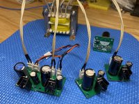
poor PCM1702s😢I usually don't get down to business right away, but I couldn't resist.
one PCM1702 needs 7 electrolytes from 47uF to 100uF, 4 for decoupling and 3 of better quality with a small leakage current for internal references
Attachments

- Home
- Source & Line
- Digital Line Level
- DAC AD1862: Almost THT, I2S input, NOS, R-2R