If R1 was ever totally shorted by accident in a disaster scenario, then "current limit" would be the capacity of the transformer & the diodes only stopped from burning down by a primary fuse and/or the electrical installation's breaker
Salas increased R1 to 1 ohm and silent as a grave. Of course not feeding Cronus + pcm2dsd, only pcm2dsd
It seems that the 30VA R-Core didn't like 1A pull at all. Demonstrated by mechanical singing. Has slightly loose bobbins grip on the core by any chance?
0.6V/2.32Ω=0.26Α thus 4.7W output power limit at 18V Vout
Metallic pad of M1 connected to drain internally.
So it seems I shorted R1 ouput to M1 drain.
Simulations shows different figures.
But anyway I am glad everything went okey in the end. 🙂
Attachments
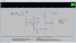
In this case the CCS doesn't work and max pass current is simply Vrectified-Vout/2.32Ω i.e. allows >> Ampere blowing a fuse and/or melting something down. Some medium size bridge diodes and R1 would basically break down quickly. Q1 over-currents also. Tx gets hot, its plastic wrap if toroid starts to shrink, M2 eventually bursts, etc. etc. If not fused.. disaster.
I felt heat like from an old oil heater and dry air smell.
All output transistors except Pos M2 was warm but M2 burned my finger throu heatsink.
I shut down power. Then got curios how hot it was, brought IR thermoreter and tested it the second time. (not a good idea)
After temp at M2 heatsink exceed 100 Celsius I shut power down again and start thinking what could go wrong.
Found it pretty quick.
Daft Punk's Get Lucky soundtrack playing in the background or not, your Ubib proved tough.🙂

Really I didn't checked.It seems that the 30VA R-Core didn't like 1A pull at all. Demonstrated by mechanical singing. Has slightly loose bobbins grip on the core by any chance?
It takes to skip the board's rectification section and make a different diodes external bridge arrangement for center tapped symmetrical.
Hi Salas
It is singing, at first try. Only planned change in next drawing is to bring the output close to the input.
Now i can put those centered tap trafos to work thanks to you.
Thank you so much Salas!
Hi Salas.
I'm really sorry for the late reply, didn't saw your question before.
For now it is feeding a iancanad i/v. Also planning to build a pre with another. As I have two more of those transformers, will see what follows than 😎.
I'm very happy with it .
Thanks again Salas 👍
I'm really sorry for the late reply, didn't saw your question before.
For now it is feeding a iancanad i/v. Also planning to build a pre with another. As I have two more of those transformers, will see what follows than 😎.
I'm very happy with it .
Thanks again Salas 👍
I built a pair of these as 5 volt USB connection power supplies using Salas' SSLV1.3 UltraBiB shunt regulator.
One for me and one for a friend that lives in Mexico who used to own a high-end audio store in Tampa, FL.
He came to visit and compare the two power supplies on a DAC-R.
The power supplies were built with the same setup as follows:
Antek AS-1212 - 100VA 12V Transformer (both secondary windings were paralleled): Antek $26
Triad Magnetics C-56U 35mH , 2A, .79 Ohms: Mouser $16.72
Salas SSLV 1.3 Power Supply board: Using 16V 47,000uF cap
The choke was used as a choke input filter on one supply, replacing the .33 ohm resister #rf. The other was built the usual way with rf in place.
Both supplies had the choke mounted, but only one was connected. I then installed the covers and could not tell which one was which from the outside as they weighed the same and had the same number of screws, etc. Months when by and I totally forgot which was which.
I have attached photos of the same supply connected both ways:
I took voltage measurements across the choke filtered supply


both AC (5.10 volts) and DC (.491 volts) and showed the out put voltage 5.10 volts DC. These were measured without a load.
After listening tests were conducted we decided the choke input supply had better depth and a darker back ground. By the end on the week, I connected the other supply as choke in put and took these pictures.
I would be interested in hearing from anyone with experience with choke input power supplies vs cap input supplies.
The idea came from a commercial product that touted the design. JS-2 linear power supply (picture attached at the end).
By the way we are using a Raspberry Pi with 8 gig memory and a HiFiBerry Digi+/Standard Version hat running MoOde Audio Player software to run the DAC R.
The DAC R has a 9 step volume control on top that allows you to by-pass the preamp and directly connect to your power amp.
One for me and one for a friend that lives in Mexico who used to own a high-end audio store in Tampa, FL.
He came to visit and compare the two power supplies on a DAC-R.
The power supplies were built with the same setup as follows:
Antek AS-1212 - 100VA 12V Transformer (both secondary windings were paralleled): Antek $26
Triad Magnetics C-56U 35mH , 2A, .79 Ohms: Mouser $16.72
Salas SSLV 1.3 Power Supply board: Using 16V 47,000uF cap
The choke was used as a choke input filter on one supply, replacing the .33 ohm resister #rf. The other was built the usual way with rf in place.
Both supplies had the choke mounted, but only one was connected. I then installed the covers and could not tell which one was which from the outside as they weighed the same and had the same number of screws, etc. Months when by and I totally forgot which was which.
I have attached photos of the same supply connected both ways:
I took voltage measurements across the choke filtered supply
both AC (5.10 volts) and DC (.491 volts) and showed the out put voltage 5.10 volts DC. These were measured without a load.
After listening tests were conducted we decided the choke input supply had better depth and a darker back ground. By the end on the week, I connected the other supply as choke in put and took these pictures.
I would be interested in hearing from anyone with experience with choke input power supplies vs cap input supplies.
The idea came from a commercial product that touted the design. JS-2 linear power supply (picture attached at the end).
By the way we are using a Raspberry Pi with 8 gig memory and a HiFiBerry Digi+/Standard Version hat running MoOde Audio Player software to run the DAC R.
The DAC R has a 9 step volume control on top that allows you to by-pass the preamp and directly connect to your power amp.
Hi, nice work and nice pictures.
Choke input will typically provide more regulation with more voltage loss on same secondary. See attachment (by Hammond).
*Regulation meant as less change in supply voltage for change in load current.
So we should make sure DC level on the reservoir capacitor is 10V or higher for Ubib at 5V output. Either for using Rf or Lin.
In general using Lin is considered subjectively smoother. Especially in the tubes world.
Attachments

I just measured the DC voltage on the Cap side of the choke. A little low at 9.54 volts.Hi, nice work and nice pictures.
Choke input will typically provide more regulation with more voltage loss on same secondary. See attachment (by Hammond).
*Regulation meant as less change in supply voltage for change in load current.
So we should make sure DC level on the reservoir capacitor is 10V or higher for Ubib at 5V output. Either for using Rf or Lin.
In general using Lin is considered subjectively smoother. Especially in the tubes world.
I may need to up the transformer a bit?
Next one is 15 volts AC.
Last edited:
Output load or not its the Ubib's CCS creating steady current draw from the reservoir.These were measured without a load.
Lin would be showing even more its regulative and ripple smoother merits in dynamic current draw situations like in passively filtered HV or LV supplies. Especially for Class B amplification.
Finally got my UBiB powering the MUTEC MC3+usb. The result is far beyond what I would have thought possible.
I will go into a little detail in case there are others who want to do this.
I am using a 200 Ah 12 volts battery which also supplies an inverter for the computer and DACs. The UBiB is connected to the battery directly - I am using four 100uF nonpolar Black Gates as a reservoir. I have had them for years and figure this is a good place for them. The battery was there so why not use it? The drop is what UBib needs for a 6 volts regulator. I ended up with 6.1. The original smps supplied 6.3 volts per the manufacturers specifications. I did not measure it.
I removed the internal smps a couple of months ago and was using a Windsong regulator based on something slightly better than the ubiquitous LM317 - I cannot recall the model name.
I was kind of surprised that the difference was so small but we get used to this in audio when tiny steps are better than nothing. I knew I would eventually use something else and then it occurred to me - Ultra BiB.
After making about every mistake one could, which does have the side effect of learning, with the patient counsel of our renowned Chief Moderator along with being audio's Santa Claus except this Mr. Clause distributes his gifts year round, I got the thing attached after very careful testing with a resistor load and then to the MUTEC the change in sound was truly beyond belief. No small beer with this. This was an improvement on the level of placing the MUTEC in the chain initially. The terribly overused word, astonishing, can be said without hyperbole.
No expectation bias here; I expected it to be better but would not have expected this result.
So yet another with deeply felt gratitude for this regulator and its creator.
I used a large chunk of heat sink - a two inches thick by 6 x 5 inches of finned heat sink. R1 is 0.75R. I used DIYaudio store insulating pads. Another name I cannot recall.
I thought the heat sink would be warm at best - instead it is not HOT but well beyond warm. I must leave this on all of the time to keep the clock circuit at its best. After leaving it on overnight it is not as hot as my SIT heat sinks but not too far away. I do not leave the SIT amps on!
I am wondering if this means I am throwing away too much power and if I need to raise R1 a bit? I have not taken a reading of the voltage across R1. I will post that as soon as I do it. Could not wait to express by appreciation for what UltraBiB can do in this case.
I did replace the Vrr and Vr1 with a pair of resistors in series. I needed 586R and luckily had a Caddock MK and a Texas Components Z foil on hand . I did notice much better voltage stability with these in place. One could get Texas Components to make any value resistor which might be overkill.
If I change the value of R1 I assume this will affect the value of this resistor. Let me know if this is correct, please.
It had been a long time since I had to make myself turn the system off. Everything I played revealed new details. The string sound was simply beautiful and guitar distortions having much greater character and nuance.
Not to neglect TEABAG - who without his boards and parts kit this whole thing would be much more complicated. What a great team he and SALAS have become.
Thanks very much.
- Home
- Amplifiers
- Power Supplies
- Salas SSLV1.3 UltraBiB shunt regulator