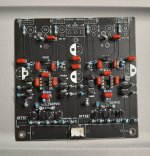
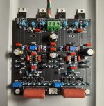
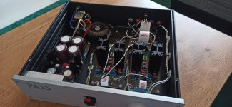
Added the electrolytic caps, film input caps and the output resistors. Getting closer. (Build progress picture attached.) Discovered one silk screen note/annotation rotated 180 degrees. (But all connections are correct, just the added silk screen annotation/note.)
Attachments

It might be tricky to remove those socketed DIPs after they are inserted. Closely surrounded by four fat orange capacitors, they're not going to give you a lot of maneuvering room, to operate a chip extraction tool.
https://www.grainger.com/product/OK-INDUSTRIES-Extraction-Tool-23Z408
https://www.grainger.com/product/OK-INDUSTRIES-Extraction-Tool-23Z408
True. Perhaps in a revision I can move the label for the bias trimmer and then move the film cap above the socket.
How far away will the power supply be from the amplifier board? Prefer to avoid long ground wires shared by two power rails myself. Others may feel differently of course.
It depends on the chassis. If the chassis is large enough the power supply board and HPA-1 board can be separated by about one inch with the power transistors bolted to the aluminum chassis floor/plate. The regulator output connector then wires over "directly" to the HPA-1 input. (About 2" wires.)
Now it probably is not advisable to do this but the regulator board can mount above the HPA-1 board and the regulator output connects top down to the HPA-1 board under it. Both boards are 10cm by 10cm.
The four 220uF capacitors could be increased if we are concerned but I was not expecting much AC current in a Class A design. Is that a mistake/misunderstanding? Maybe it would be interesting to put my 60 dB LNA across the ground wire/small sense resistor and see what is there. Something to try in my ample spare time.
Last edited:
Seems reasonable to expect fairly constant current draw. My personal preference to try to stay on the cautious side, is all....was not expecting much AC current in a Class A design. Is that a mistake/misunderstanding?
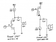
Here are the schematics of Nelson Pass's two VFET amplifier variants, which diyAudio sold as complete kits in April and June of this year. Both of them are class-A and both of them are single ended.
HOWEVER
Only one of them draws a constant current from the +36V power supply, i.e. supply current is fixed and completely independent of signal. The other amp's supply current DOES vary with signal; if you apply a square wave to its input, its power supply current is a square wave + offset. Definitely NOT a constant current. The bigger the input square wave, the bigger the supply current square wave.
These serve as a counterexample to the claim "All Class A amps have constant current draw". Delightfully, they are also a counterexample to the claim "No Class A amps have constant current draw."
_
Attachments

Seems reasonable to expect fairly constant current draw. My personal preference to try to stay on the cautious side, is all.
I should explain that some of my implementation choices are driven by my current budget. Otherwise I would be quite happy to make one larger board and in fact design it as two mono-blocks with two completely independent power supplies with dual secondaries for each.
However not all is lost due to budget constraints. One of my boards is assembled and two are partially assembled. I can actually run them as dual mono-blocks with independent power supplies after the second is assembled. [But that is likely overkill?] I have two of the mixing console power supplies that I am using and the regulator boards are a batch of five boards. Although I am not sure I would be able to hear the difference? That said I really like the two KSA-50 clone mono-blocks I made. I plan to split my MA9S2 clone into two mono-blocks when I get a chance to get back to it.
I have also assembled two of my DAC boards and I later plan to run those as dual mono also. Right now I am only using one in stereo mode.
Last edited:
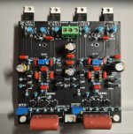
Everything seems to be working properly. I started with the bias servo disabled and with the bias pot at maximum resistance. Bias pot was oriented so that clockwise rotation increases the bias. Fired up with about 20mV offset which was easily adjusted to 1mV with the potentiometer. Bias was set, readjusted offset and then installed the op-amp and enabled the offset servo. Offset is very low.
For now I am using spring steel clips to clamp the transistors to a heatsink during testing. Later they will attach to the aluminum chassis floor.
For now I am using spring steel clips to clamp the transistors to a heatsink during testing. Later they will attach to the aluminum chassis floor.
Attachments
Last edited:
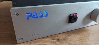
I don't know how many people are following my thread in the Headphone Systems forum. I got my version of the HPA-1 running last night using an old bench power supply. I call it the "A3" because it is, as Jeff Young said, not a true clone but more of a "sibling" to the HPA-1. I didn't want to infringe on Pass Labs trademarks with the name on the board.
Sound is quite promising and very different from what I'm used to hearing. I will reserve further judgment until I get a proper power supply built.
One note on Jeff's schematic: As drawn, the bias pots work in reverse, so turning clockwise lowers the current. I changed the orientation on my board.
I wanted to ask a question about the input attenuator impedance. Jeff's schematic shows a 100K volume potentiometer, which seems high given the 100K input resistor to ground. I was wondering if this value is authoritative, or just a guess. I am used to using lower-impedance attenuators.
The reason I ask is I have a nice 100K Elma stepped attenuator here that I could use. I was curious if anyone had any opinions.
Thanks.
So how are your guys clones sounding? I must admit I've been using mine as my primary pre-amp for a couple of years now with no desire to touch it. It's been through many a power outage, brown-out, etc. without any hitches.
The sound is perfect. Better than Headamp with ECC88-6AS7G, Earmax, better than LME49600+LME49720.
Preamp is also excellent.Detailed sound in the entire band. Bias 120mA per channel.
Thanks guys
Preamp is also excellent.Detailed sound in the entire band. Bias 120mA per channel.
Thanks guys
The review in stereophile speaks:
"The input impedance measured a usefully high 46k ohms at 20Hz and 1kHz, dropping inconsequentially to 40k ohms at 20kHz"
So when you know that there is an input resistor of 100k a 100k pot in parallel could give the values stereophile measures.
So your Elma should do a good job.
:--))
.........
I wanted to ask a question about the input attenuator impedance. Jeff's schematic shows a 100K volume potentiometer, which seems high given the 100K input resistor to ground. I was wondering if this value is authoritative, or just a guess. I am used to using lower-impedance attenuators.
The reason I ask is I have a nice 100K Elma stepped attenuator here that I could use. I was curious if anyone had any opinions.
Thanks.
This is an older picture. I ended up with a 20K EIZZ attenuator from China which I rebuilt for 20K Ohms using Vishay RN50 metal films in place of the not-so-great sounding carbon films that came stock. I think it's more appropriate to use the lower-value attenuator given the 100K bias resistor at the input. There are more details of my build on the Headphone Systems subforum.
The amplifier sounds pretty good, but isn't the last word in transparency or neutrality, IMHO. Granted, I didn't use the official power supply and have caught criticism for that. I'm skeptical because the Super Regulator is a fine design and works great in my other projects. I have no idea how this thing compares to other clones, or a real HPA-1. I would say it has a "different" sound which may or may not appeal to you depending on what you're looking for. It's quite listenable and not at all the disaster described on that audio "science" satire forum. Otherwise, I've decided it's best not to try too hard at playing golden-ear games because someone will always take exception, no matter what you say.
"It's entertainment, not dialysis."
For kicks, I removed the 4.7K load resistors from the driver and the 330pF compensation capacitors. This increases loop gain by about 50dB.
Blasphemy!
Amp is completely stable without compensation. (Presumably there's more than enough capacitance looking into the output MOSFETs.)
Listening to it now. I don't want to offend anyone by describing what I hear.
-Henry
Last edited:
- Home
- Amplifiers
- Pass Labs
- Pass HPA-1, what do we know?