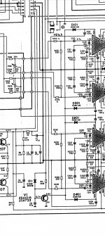
It still distorts with transistor removed.Forget by a moment transistor biases. Speaker's outputs still distort?
I would live in a jar with boiling nitrogen. Pufffff....
Yep, voltage where emitter should be is 6.1v... should I remove the diodes to see wich ic causes this as datasheet states 3.5v?Buah.... False alarm. Now replace IC's. There isn't any other possibility.
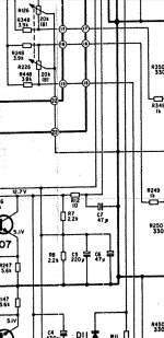
Difficult to say. Diodes are ORing toguether all mutes pins. So no reason to pass the distortion from one chanel to other through those diodes. Transistor is a emiter follower pulling down muting pin during the time constant at base is under the internal voltage of TA pins. Once this time expires, emiter goes up and all pins float at their own level.
Oh, ok. I didn't understand this muting circuit completely. But now that you approved what I was thinking about I see that amp cant be muted externaly, mute wire going to the DIN rather mutes the radio, or another scenario is that the radio sends 12v thru DIN to the amp/eq, so you don't need to connect ACC + wire to the amp/eq, just the supply and gnd.Difficult to say. Diodes are ORing toguether all mutes pins. So no reason to pass the distortion from one chanel to other through those diodes. Transistor is a emiter follower pulling down muting pin during the time constant at base is under the internal voltage of TA pins. Once this time expires, emiter goes up and all pins float at their own level.
Ok.Ok. This is for preventing pops while energizing the set.
I slept over and here is the plan:
I will try to make pre/eq and use seperate amplifier.
I will do this modification in the way, that I will be able to reverse it if setup wont work as it should.
I have 2 pairs of inputs on the DIN connector. 2 will remain, other two will become outputs. I will achieve this by removing the 15k resistors and I will be left with pads to wire in output wires.
Wiring will be custom made, from DIN to the amp and to the radio. No connectors in between, just RCAs directly on the radio & amp.
I will lift the gain by increasing value of pull-down resistors, R103 and R105 as @Perry Babin suggested.
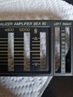
Preamp / eq should stand higher gain as VU level indicators suggest that higher levels are expected.
If for any reason higher gain will cause distortion, I will revert the resistors and make 4558 preamp at the output of the eq.
I had already removed speaker level input wiring and I had disconnected ACC 12v wire from the DIN connector, as I wont use it and it can only cause noise...
The only thing I do not understand is the balance circutry.
Wipers of the pots goes to the muting circutry...
Can I hook them to gnd?

Last edited:
IMO they are grounded as is. Perhaps the drawer omited the small black circle usualy indicates joining or soldering or is not so clear in the schematic.The only thing I do not understand is the balance circutry.
Wipers of the pots goes to the muting circutry...
Can I hook them to gnd?
Ok, will try as is.IMO they are grounded as is. Perhaps the drawer omited the small black circle usualy indicates joining or soldering or is not so clear in the schematic.
Will do. Now I'm adjusting the gain and will solve this first with amplifier still wired in to make sure it wont cause any problems. I had tryed 10k resistors l, but will go to 5k, 10 is a bit overkill.Take a confirmation with the ohmeter to be sure.
It outputs almost 6vpp without any clipping, with eq set to about +9db... I'm impressed.
The resistors should be R103 and R203. I misread the original diagram. If you actually changed R205 to 10k, I'd expect a loss in output.
You should be able to break the connection to N1 with no affects on the preamp output of the op-amps. That said, the op-amps are driving 3.9k ohms to the fader pots and that load should not affect the output of the op-amps if the connection to N1 is left as-is.
You should be able to break the connection to N1 with no affects on the preamp output of the op-amps. That said, the op-amps are driving 3.9k ohms to the fader pots and that load should not affect the output of the op-amps if the connection to N1 is left as-is.
Yes, I figured... I'm at 4.7k now, but still too high... looks like 2.x k will be the way to go.The resistors should be R103 and R203. I misread the original diagram. If you actually changed R205 to 10k, I'd expect a loss in output.
You should be able to break the connection to N1 with no affects on the preamp output of the op-amps. That said, the op-amps are driving 3.9k ohms to the fader pots and that load should not affect the output of the op-amps if the connection to N1 is left as-is.
N1 is actually 2 pin connector, but if I break it there, I will loose the balance fader. I will break the connections right after the balance.
Schematic makes it complicated. This is balance, it acts like balance control and I think that this symbol stands for balance.Balance is left/right. Fader is front/rear. The control is front/rear. Are you going to use 4 pins on the din for outputs?

I was staring at the schematic yesterday and wondering how this acts like a balance pot myself.
I don't understand it... unless somebody was inthere before and wired something wrong, like inputs to the power ics maybee...
I will use just L / R outputs, I don't need F / R separation.
Oh, ok, I see.In the copy from @Perry Babin it is OK the grounding of the balance pots.
But in scematic it is presented as a fader, and it's actual function is balance...
Am I missing something here? This really got me confused.
- Home
- General Interest
- Car Audio
- Blaupunkt BEA80 / TA7270P ic

