I noticed in catalogues offering Inductors, on offer were Inductors with the same mH value but differing in AWG.when you intend to make such a large change in inductor value?
Does diameter of a copper winding affect sound reproduction?
A number of things change, but the only thing you'll notice on a woofer is the resistance. The response can change a little...
Very thin wire can create a problem with heat when used with a low sensitivity woofer.
Very thin wire can create a problem with heat when used with a low sensitivity woofer.
A high resistance coil in series with your woofer will mean the amplifier will have less control over the woofer at its resonant frequency, possibly resulting in a 'boomier' sound.
Resistance decreases with increasing wire diameter.
An air coil of the same inductance as an iron core coil requires more turns (greater length) of wire which must be thicker to achieve the same resistance as the iron core coil.
Resistance decreases with increasing wire diameter.
An air coil of the same inductance as an iron core coil requires more turns (greater length) of wire which must be thicker to achieve the same resistance as the iron core coil.
Should I measure the resistance of these coils to ensure their suitability?A high resistance coil in series with your woofer will mean the amplifier will have less control over the woofer at its resonant frequency, possibly resulting in a 'boomier' sound.
Resistance decreases with increasing wire diameter.
An air coil of the same inductance as an iron core coil requires more turns (greater length) of wire which must be thicker to achieve the same resistance as the iron core coil.
Also, are coils directional, regarding whether I use the wire from the beginning of the wrap or the end of the wrap?
You do not have the full information about a coil unless you measure its DCR.
And coils are not directional.
And coils are not directional.
I think saying this may give the impression that something's wrong when it isn't (I understand it is often said).will mean the amplifier will have less control over the woofer
Would you say that a low Q resonance has too much control over the woofer?
The driver itself doesn't change with an increase in source resistance, but simply has a drive Voltage which is proportional to the driving and driven impedances.
In any case, the dominant factor in the amount of damping is the driver resistance.
Last edited:
I'm simply saying things in a way that Cliff might understand.
I wasn't suggesting that something would be wrong, but that there would "possibly" be an audible difference.
The DCR of the inductor would ideally be zero, thus taking it out of the equation entirely.
I wasn't suggesting that something would be wrong, but that there would "possibly" be an audible difference.
The DCR of the inductor would ideally be zero, thus taking it out of the equation entirely.
We couldn't live in a world without parasitics. It's just a matter of keeping them within tolerances.The DCR of the inductor would ideally be zero,
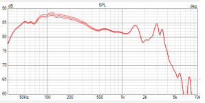
To keep Cliff in the loop, the curve appears to show the effect of series inductor resistance on the response of a woofer. I'm seeing only around 1 dB overall variation, i.e., only a small difference between the inductors. For completeness, it would be nice to know the impedance of the woofer used in this test.
The higher the nominal impedance of a driver shouldn't the in-series DCR be lower for the same effect?
Trying to get the DCR of an inductor down to 5% of a drivers nominal impedance with larger values empties a wallet more quickly.
I've always thought that many speaker commercial designs cross between the woofers and the midrange at 500 and 800 not for sonic benefits but to keep crossover costs within reason to maximise sales and profits, also from a commercial POV crossing higher means you can use less robust and cheaper midrange drivers in 3-Way speakers.
Less of an issue in 2-Way speakers naturally
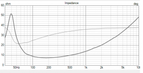
That's right, same inductance, different resistance. Here's the impedance.the curve appears to show the effect of series inductor resistance on the response of a woofer.

Against a higher impedance driver, the series impedance can be higher too... Larger inductance, larger resistance, smaller capacitance.The higher the nominal impedance of a driver shouldn't the in-series DCR be lower for the same effect?
If you have a lot of resistance you can stuff your box to lower the system Q and get back to the original response.
Another option is to use an iron cored inductor.
Thanks to all.
I started by adding the 1.21mH air core inductor in series.
I found no sonic difference that I could hear.
I might try fully replacing the existing 1.72 Iron Core Inductor with the harvested 3.84mH Iron Core Inductor.
This should reduce the possible effects of having 2 Inductors in series and its value will be close to the 3.44mH target.
I wonder what the sound is like without a bass inductor? 🤔
Plugging your available bass inductor values into a simple response simulator suggests that the original 1.72 mH value, although not optimum, gives the best result of the bunch. In conjunction with your 2nd order high pass filter of 3.94 uF (Ted's parallel 2 uF capacitors) and 0.31 mH air core inductor, it gives a crossover frequency of 2,950 Hz.
However, that is simply working with the components available and in the absence of driver parameters - so only your ears can decide.
I hope we're getting close to a resolution. 🙂
Hi Galu.
I asked a listener who's in his early twenties to appraise the difference adding the air core Inductor to one of the Rotels.
He said it was very close, but the modified speaker was duller sounding.
When I have more time I'll either experiment further (a. try with no Inductor, b. try with more powerful Inductor, or c. Just restore to standard).
I'll see how I go.
🙂
So, to be quite clear, what mH value inductor was in series for the 'young ears' test?
I ask because you mention "adding the air coil inductor" in the above post.
The first and most obvious thing to do, is to try with no inductor at all. This would provide you with a baseline reference.
I ask because you mention "adding the air coil inductor" in the above post.

The first and most obvious thing to do, is to try with no inductor at all. This would provide you with a baseline reference.
I felt adding the 1.21 mH air core inductor in series avoided the negatives associated with the magnet.So, to be quite clear, what mH value inductor was in series for the 'young ears' test?
I ask because you mention "adding the air coil inductor" in the above post.
The first and most obvious thing to do, is to try with no inductor at all. This would provide you with a baseline reference.
But the total mH value didn't take inductance to the prescribed doubling prescribed.
Next test will be without Inductor & maybe after that the 3.84 Inductor.
Fingers crossed. 🙂

- Home
- Loudspeakers
- Multi-Way
- No sound from one of the Rotel RL 870 Speakers?
