I wouldn't use them in new circuits, but I certainly wouldn't throw them away either.Speaking of capacitors, I have a new victim on the bench. This Nakamichi CDC-3a will give up its TDA1541a and the Signetics 5532s for sure. Are the red poly decoupling caps or blue timing caps worth using in a DAC?
Last edited:

Guess we went full macgyver over here 😅I've split the Salas Ultrabib clone boards and use just the positive side also 😉
I certainly wouldn't solder them to that position, it's up to you to decide.hello @grunf , i have a spare miro1862 board which i have installed c15 with tantalums. I have not tested the board yet. Do you think i should change out the tantalums?
I have tested many tantalums (solid and polymer) and have not found issues with leakage current. I use them also in my DS dacs in Vref circuits where they work well since they are not microphonic like class 2 ceramics.I agree that there are smd tantalums with low leakage current, not all types, mostly high temperature automotive and industrial types, but they have their disadvantages compared to standard (audio )electrolytes.
I don't know if you tested them for leaks, but I did last summer at the suggestion of Walt Jung, and I was really surprised by the results. Some of the types we like to use are truly disastrous, such as polymers of any type.
This leakage does not bother with decoupling, on the contrary, I use OS-CON and similar types, but with references, some regulators, tubes and more sensitive analog circuits, I avoid them in a wide arc.
If you have a Walt Jung superregulator I suggest you do a test with the cap in the reference filter, I was of the same opinion as you but Walt quickly dissuaded me after doing a couple of tests in my audio system.
For example, in my new 5V regulator (Walt Jung UnivReg_122714), OS-CON is still decoupling because it is a regulator for a digital filter, but at the input of the op amp. are two UKZs operating at 1/25 of the nominal voltage so the leakage current is well below 0.1uA.
And believe me, you can hear it in a audio system🙂
I did the tests according to the instructions from Walt's article and tantalums and polymers did not really show up in comparison with UKZ.I have tested many tantalums (solid and polymer) and have not found issues with leakage current. I use them also in my DS dacs in Vref circuits where they work well since they are not microphonic like class 2 ceramics.
I use SMD tantalums and polymers in digital circuits where it is necessary to suppress noise in the RF area, but they are bad in the LF area, and in my opinion, sometimes the area below 100Hz is very important for quality audio reproduction, especially for voltage references. With references with low noise (2-3nV/Hz) that I use, the choice of components plays a big role.
I never use class 2 ceramics and any smd capacitor near analog signals, the only exceptions are COG and acrylic film smd (FCA).
Last edited:
I agree. The references I use for Vref have even lower noise and they use tantalums. Not throughout but in critical places.With references with low noise (2-3nV/Hz) that I use, the choice of components plays a big role.
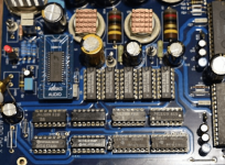
😍Miro, another one pcm63p-k done 🙂 Hats down to you, this is a beast! Now just to 3d model a proper case, and off to cnc milling 😊
View attachment 1115244
@miro1360 @Vunce @codyt ,
Just wondering what's the lowest dc offset possible for your tda1541.
I have completed two boards, one board can be trimmed to 0.6v and another 0.455v
and i can see that the tuning the variable pot does not make much difference for both boards.
i believe the dc offset should be able to get down to the mV range? Both tda1541 chips work properly in my another day which has the opa2604 as output but without dc offset adjustment since the output is cap coupled.
Is there any known disadvantage to using a socket for the dac chips rather than soldering directly to the board?
What sockets have other people used?
What sockets have other people used?
Last edited:
Soldering is the king. It even rhymes 🙂 But quality socket is really close. Go with mill max and you won't regret it.Is there any known disadvantage to using a socket for the dac chips rather than soldering directly to the board?
What sockets have other people used?
Again crying smiley cute.@Zoran I know him under nickname "Nemo" from another forum. You can recall our old conversation about that design:
https://www.diyaudio.com/community/...et-binary-no-cpld-no-fpga.341478/post-5885606
... He send me his altera files, I tried his design as glue logic from SMD components and it did not work for me (I assume timing problems). In CPLD it can work but I have not tried it.
That is why I created different design, more glue-logic friendly approach. I tested and debugged it for a long time until it started working.
Creating the working glue-logic is pretty hard, because of timing issues. Altera simulation sometimes does not match the real glue-logic.
A lot of not-working prototypes are in my altera folder 🤣
But that is not true the guy have had already done discrete design muche before based on his own altera FPGA design...
This is from new site but the photo is from maybe 10 years before the new commercial site established...
Attachments
With Current injection of 2mA. I trimmed the offset with numerous TDA1541A to 0mV. And it remained constant stabile.@miro1360 @Vunce @codyt ,
Just wondering what's the lowest dc offset possible for your tda1541.
I have completed two boards, one board can be trimmed to 0.6v and another 0.455v
and i can see that the tuning the variable pot does not make much difference for both boards.
i believe the dc offset should be able to get down to the mV range? Both tda1541 chips work properly in my another day which has the opa2604 as output but without dc offset adjustment since the output is cap coupled.
These values are huge (045V-0.60V)... Take a look at the data sheets abs of 0.025V is recommended as max offset.
Zoom,
My TDA DAC dc offset easily trims to 0mV, you need to send an input signal to the dac while adjusting.
My TDA DAC dc offset easily trims to 0mV, you need to send an input signal to the dac while adjusting.
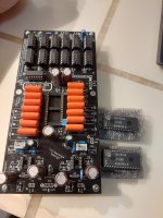
27R Passive IV + 100x JFET Gain Stage
https://www.diyaudio.com/community/...st-tht-i2s-input-nos-r-2r.354078/post-7160371
Exactly a month later, proper PCBs arrived. 🙂

Patrick
https://www.diyaudio.com/community/...st-tht-i2s-input-nos-r-2r.354078/post-7160371
Exactly a month later, proper PCBs arrived. 🙂
Patrick
I guess i am doing things incorrectly.With Current injection of 2mA. I trimmed the offset with numerous TDA1541A to 0mV. And it remained constant stabile.
These values are huge (045V-0.60V)... Take a look at the data sheets abs of 0.025V is recommended as max offset.
And when the chip got his thermal playback stability...trim after 5 minutes of playback.Zoom,
My TDA DAC dc offset easily trims to 0mV, you need to send an input signal to the dac while adjusting.
I also was able to achieve 0mv. However, I had numbers like yours when I started initially. The trick is that your source needs to be hooked up before dialing offset. Once I applied my I2S source, it was no problem getting to 0mvI guess i am doing things incorrectly.
*edit Vunce beat me to it 🙂
with the music signal still playing too?And when the chip got his thermal playback stability...trim after 5 minutes of playback.
so the music signal need to be playing like Vunce mentioned?I also was able to achieve 0mv. However, I had numbers like yours when I started initially. The trick is that your source needs to be hooked up before dialing offset. Once I applied my I2S source, it was no problem getting to 0mv
*edit Vunce beat me to it 🙂
- Home
- Source & Line
- Digital Line Level
- DAC AD1862: Almost THT, I2S input, NOS, R-2R