Hi all,
Could you please link me the post regarding the complete procedure of setup? in particular P2 for Aleph Current Source. Thanks
Could you please link me the post regarding the complete procedure of setup? in particular P2 for Aleph Current Source. Thanks
Look back at post 158 of this thread it has a link back to builders thread to what Mr. Sample did. Set p2 to the middle of range and leave it alone, no need to adjust it. Be sure to install the adjustable power resistor , it will make it easier.


No, I refer to gate snubber on adapter pcb. Do measurements should be done without load at output like for Aleph? Thanks
Peppenino, I had a similar question during my build. As the First Watt F3 schematic lacks a gate snubber, as does the Zv9 schematics once feedback and the Aleph CCS were introduced, and as a LU1014D mounted direct to the PCB would lack a snubber, I chose not to use one. However I believe at least some other F3 builders using XRK's adapter board do include a gate snubber of 100R. I have no idea what effect if any that would make, as I have no way to measure for oscillation.No, I refer to gate snubber on adapter pcb. Do measurements should be done without load at output like for Aleph? Thanks
That, ZM. MeasurementsNo, I refer to gate snubber on adapter pcb. Do measurements should be done without load at output like for Aleph? Thanks
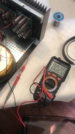
setting the amp - shorted input, no load
measuring performance ( THD Spectra, power, whatever) - logically signal in, dummy load , appropriate measurement gear
gate stoppers - always - better safe than sorry
measuring performance ( THD Spectra, power, whatever) - logically signal in, dummy load , appropriate measurement gear
gate stoppers - always - better safe than sorry

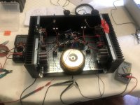
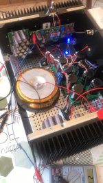
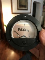
my F3 is taking shape
Attachments
-
 A916BA9B-20D4-45CB-8FAB-4FA4CB3FEEB1.jpeg401.4 KB · Views: 189
 -
 ED38A52A-23DB-41E3-9ADE-0DA5A738A9A1.jpeg392.7 KB · Views: 191
 -
 F8FEDBA7-1383-4B0B-A019-47DEBD2BAA8B.jpeg367.2 KB · Views: 185
 -
 7AE45F6D-F31D-4305-90FA-51E8B46589B0.jpeg336.3 KB · Views: 179
 -
 960619C0-E4DD-4EB0-B2A3-26A20787C592.jpeg349.9 KB · Views: 184
 -
 0C2CC5B9-5913-4C15-9086-AF38A1C1092C.jpeg282.3 KB · Views: 176
 -
 212C4111-2B6C-4F6B-B659-0C7951354C4C.jpeg286.7 KB · Views: 167
 -
 E0B1EE15-B87A-47E1-BA13-3CC4A4DF1CA1.jpeg280.9 KB · Views: 178
Hory Clap!!! That looks fantastic, can’t wait to see it all together with that meter! How is it biasing up? Bubba
Hi8/26 Update
Powered up the right channel board yesterday and all went well. I will make a couple small updates to the boards (correct a silk screen mistake and add 2nd resistor location for R5 to make it easier to parallel resistors to create the desired resistance to match a particular Q1). Due to a lack of time on my part and a lack of general interest I will not be making the second power supply board option for this group buy. Please update your desired quantities by 8/29 and I will place the order on 8/30.
Was the 2nd resistor location to fine tune R5 implemented ?
I looked briefly at my PCBs and couldn’t see it. If it’s not there I will unsolder R5 and temporarily replace it with a 5-10W pot until I find the precise value based on Q1.
Thanks
Eric
Sorry, for the immensely late response, I needed a break after the group buy wrapped up. I tried to add a second resistor location for R5 and decided that it was not worth the effort to rework the board. For my build I used the potentiometer to determine the required value, and soldered together a set of resistors and placed the set in the R5 location.Hi
Was the 2nd resistor location to fine tune R5 implemented ?
I looked briefly at my PCBs and couldn’t see it. If it’s not there I will unsolder R5 and temporarily replace it with a 5-10W pot until I find the precise value based on Q1.
Thanks
Eric
- Home
- Group Buys
- F3 Clone Board Set Group Buy