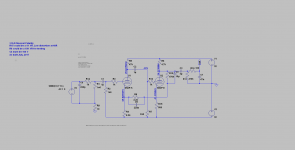
Both 2 transistor circuits are :cap multiplier and current limit.
Yes, I think in this way the filament has time to warm up before the anode goes live
It looks to me like X10-D is not an optimal tube buffer. ... Low distortion is achieved but not without rather large amount of feedback.
I agree. Too much global feedback and too many capacitors in the signal path.
A cathode follower should be a better choice. maybe dc coupled, with very few components. no GNF (only local).
Yes, a higher output impedance.
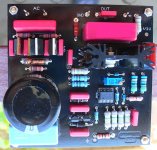
Resurrecting an old thread. I have this clone board modified with good quality caps from aliexpress and want to use as a pure preamp tube buffer with volume control. What value of the volume pot should I be using with this X10-D buffer board and I am using ECC82 tubes? I will get the DACT type 21 step potentiometer which I like the most.
thanks
thanks
Resurrecting an old thread. I have this clone board modified with good quality caps from aliexpress and want to use as a pure preamp tube buffer with volume control. What value of the volume pot should I be using with this X10-D buffer board and I am using ECC82 tubes? I will get the DACT type 21 step potentiometer which I like the most.
thanks
i guessing higher the better. 50k or 100k if the pot goes before the buffer
i guessing higher the better. 50k or 100k if the pot goes before the buffer
Thank you, yes the pot will be placed after the source selection and before the buffer. Will plan to get a 50K one DACT type eBay one 23 step ones.
Look at the website referenced very early in this thread -- specializing in upgrades to this board.
Resurrecting an old thread. I have this clone board modified with good quality caps from aliexpress and want to use as a pure preamp tube buffer with volume control. What value of the volume pot should I be using with this X10-D buffer board and I am using ECC82 tubes? I will get the DACT type 21 step potentiometer which I like the most.
thanks
Putting an unbuffered pot infront of the X10-D is basically negating the whole point of the circuit. What benefit the circuit offers is in presenting a very high load to the output stage of the CD player thus reducing distortion. Reduce that load with your pot and the benefit reduces in direct proportion.
In short this is not the correct circuit for your experiment.
Shoog
Both 2 transistor circuits are :cap multiplier and current limit.
Can't believe some are still using this device 😱 You must be hating good sound.
Hi, what do you recommend for a V-out DAC as Technics lowfi CD player?
I actually cleaned the output, little better. Even drew direct wire from the chip but nothing spacial happend. Lower output level.
Apriciate if you point out some good stage.
Regards/Amir
Power supply
Hi!
I have already built preamp in 2 copies.
If you use a 12V AC adapter, the pipes will not have enough voltage for heating - you need to measure and see.
15V AC required. The multiplier that produces the supply voltage is a joke in my opinion. It could easily be a higher AC voltage for the multiplier, or a good external supply voltage for the pipes, even higher than 100V DC, but how much should it be? Without changing the component values. Should nutrition be the plus-minus design? Can't be zero and 100 (150) V?
Excellent power supply for ARC PH3, LS7, etc. power supply, professional.
Attachments
Its guaranteed that this circuit should perform better at higher voltages, but i suspect that probably altering any aspect of it from its original design will degrade its sonic signature. When I had mine many years ago I tried replacing the Jan 6922 valves with Mullard ECC88's and it was not an upgrade - syrupy is not adequate to describe the result.
This is a highly tuned design which uses its valves so far out of their comfort zone that even changing any part has unpredictable outcomes. That unfortunately is the very definition of bad design.
Shoog
This is a highly tuned design which uses its valves so far out of their comfort zone that even changing any part has unpredictable outcomes. That unfortunately is the very definition of bad design.
Shoog
Reviving this old thread 🙂
My 12Vac walwart died, I have a 15Vac walwart PS that I can use but before I use it can someone confirm that 15Vac PS can work with the X-10D won't "stress" the voltage multiplier built in the X-10D and kill it?
Assuming it won't kill the voltage multiplier can someone predict how it will affect the whole circuit and the tubes?
Thanks
Yes. The 35V caps were already marginal. 15VAC will approach 42V, on 35V caps, and short-short life."stress" the voltage multiplier built in the X-10D and kill it?
Also don't you want 12V for the heaters?
Hi PRR, thanks.
Before the 12Vac power supply died I measured 19Vdc on the PS capacitors.
As for the heaters, the heaters connected in series, not in parallel.
Before the 12Vac power supply died I measured 19Vdc on the PS capacitors.
As for the heaters, the heaters connected in series, not in parallel.
Has anybody ever tried setting this thing up as a true buffer, that is, with no gain? Stock, R104 is 8K2 and R106 is 1K5, so the gain is 1.18x or 1.44 dB. (My unit has these resistors and the schematics in this thread show the same.)
I can clearly hear the extra gain when this is switched in/out of my preamp's tape loop. I might just bypass R106/R206 (and C103/203) with wire links.
I can clearly hear the extra gain when this is switched in/out of my preamp's tape loop. I might just bypass R106/R206 (and C103/203) with wire links.
Last edited:
@Koonw @auriga2001in Do you still have x10-D simulation file somewhere available so I could also pay with it and get the best sound out of it?

Thank you. How happy you are with this tube amp with your made changes? What could be better?Hi,
Please take a look at what I could find...
- Home
- Amplifiers
- Tubes / Valves
- Musical Fidelity X10D schematic