2sc3298 and 2sa1306 in one side are getting too hot and bias and dc offset will not adjust properly. These are the beginning stages of amp and not the outputs but are heatsinked. I see where alot of people use 2SA1837 and 2SC4793 as direct replacements in many amps but what concearns me is the collector current is 1.5 in originals and only 1 amp in replacements. This amp is too valuable to gamble with if it could cause damage. Has anyone replaced these in this amp with success? Is the collector current OK to be lower in this case? I cant find genuine replacement for originals only chinese stuff on ebay which I dont trust. Thanks
Last edited:
Hi,
Why did you replace them in the first place ? Something went bang ? Btw, here is the service manual. Check all those voltages. What is the idle current ? According to the service manual, it should be around 40mA per transistor. Btw, what do you mean you can't adjust the bias and offset ? Are the readings all over the place, unstable ?
Why did you replace them in the first place ? Something went bang ? Btw, here is the service manual. Check all those voltages. What is the idle current ? According to the service manual, it should be around 40mA per transistor. Btw, what do you mean you can't adjust the bias and offset ? Are the readings all over the place, unstable ?
Attachments
I havent replaced them yet but just trying to see if these would be suitable replacements. There is something wrong in bias circuit. I have the PA7II version which also has adjustable dc offset. Many do not have adjustable dc offset. The problem I'm having is The Bias will stay at 2.1mv and not adjust at all unless you bring up the dc offset to over 50 mv. Also when you do get bias at correct 40mv these 2 transistors are really really hot compared to the other side. The amp will play but this side gets hot real fast and just wanted to take care of it before it causes other problems.Hi,
Why did you replace them in the first place ? Something went bang ? Btw, here is the service manual. Check all those voltages. What is the idle current ? According to the service manual, it should be around 40mA per transistor. Btw, what do you mean you can't adjust the bias and offset ? Are the readings all over the place, unstable ?
We can't put the blame on those two transistors (probably they're ok) yet. Check those voltages as shown in the service manual.
Just to confirm my understanding, the hot transistors are Q114 and Q115? And the well-behaved channel does not exhibit the peculiar need for large output DC to achieve proper bias current?I havent replaced them yet but just trying to see if these would be suitable replacements. There is something wrong in bias circuit. I have the PA7II version which also has adjustable dc offset. Many do not have adjustable dc offset. The problem I'm having is The Bias will stay at 2.1mv and not adjust at all unless you bring up the dc offset to over 50 mv. Also when you do get bias at correct 40mv these 2 transistors are really really hot compared to the other side. The amp will play but this side gets hot real fast and just wanted to take care of it before it causes other problems.
Assuming the above is correct, I suggest studying the good channel's behavior to learn what should be expected in the problem side. As both High Tech and gto127 noted, the bias current observed flowing through R136 (eg. 40mV) should be similar across all the 1 ohm resistors (i.e. R130,R132,,,,R142 and R131,R133,,,,R143). But for more complete insight, I recommend adjusting VR11 for minimum bias current and noting how emitter voltages grow with advancement of VR11 setting. (eg. Q114,Q116,Q118,Q120,,,,Q132 and their mirror image pairs Q115,,,,Q133). I believe there will be very little sensitivity to output offset tweaks.
Then repeat the same bias exploration on the problem channel. I anticipate very different behavior as bias current is advanced. Try to spot the discrepancy between channels. My wild guess is that one or more of the output transistors has failed.
Good luck!
Last edited:
*bump
If I understood him well, the amplifier works but it gets hotter than the other channel although he hadn't been specific, was the amplifier at full load or the heating began on a lower music level. Besides if one of those output transistors has failed, in almost all cases the full DC would appear on the output.
My wild guess is that one or more of the output transistors has failed.
If I understood him well, the amplifier works but it gets hotter than the other channel although he hadn't been specific, was the amplifier at full load or the heating began on a lower music level.
Besides if one of those output transistors has failed, in almost all cases the full DC would appear on the output.
Last edited:
You're probably right. I keep trying to think of a defect that would explain his symptoms. I speculate that Q114 and Q115 are having to deliver output current without benefit of current gain in the output devices--- but a good explanation eludes me.
The transistors in question are the predrivers. If one of the drivers (Q116-119) were shorted base to emitter you would get the symptoms you describe. “Works, but the predrivers run hot”. It would also bias at a different setting, perhaps not get to the target at all. I had this happen on an EF3 amp (solder bridge on the PCB) and it caused a lot of head scratching before the cause was discovered. Ran it that way for almost a year.

Sorry it took awhile to get back. I had to run jumpers to the side tested in order to test the voltage as it's just too tight to test everything when fully put together. The voltages are correct on all transistors on the input stages with exception of Q139. the + and -.8 volts on emitter and collector are .63. The base is very close to 0 instead of the .2 volts it should show. Is it possible the thermal limiter is bad?
I should have been more clear on this. When I adjusted it previously I cut dc offset slightly above 50 mv so I could adjust bias to the proper level(40mv). I had assumed sightly above 50dc would have been ok. I ran it with music for an hour. The affected side was so hot you couldn't hold hand on for very long. It was after that when I took apart I discovered the 2 transistors I mentioned in beginning were the first to get hot. If I do not cut dc offset above 50 the bias stays at 2.1 vollt is unadjustable and that side stays cool even if on for awhile.*bump
If I understood him well, the amplifier works but it gets hotter than the other channel although he hadn't been specific, was the amplifier at full load or the heating began on a lower music level.
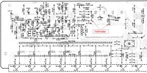
Hm, it might be the issue with the pre-drivers (Q116/Q119) as wg_ski pointed out. Before that I would check the Vbe multiplier (Q139) and observe its behavior. First (you have to bite the bullet anyways) dismantle the affected channel as shown in the service manual. If the input cable is too short you have to unscrew the RCA connector and probably you would have to desolder the ground wire as well (from the grounding point). Beware, when RCA is dismantled and the ground is cut and if you turn the amp on, a serious damage will occur (fried output transistors). So, be sure to solder a piece of wire between the ground point and the ground on the connector. Check the grounding with an instrument. Better safe than sorry ! Btw, you forgot to tell us which one is affected, the L or R channel ? So, attach a voltmeter at the points shown in figure 2 and one on the output. Btw, it's good to have two instruments for this kind of tests. Probes with clips is mandatory. Turn down the BIAS trimpot first. Adjust the offset voltage as close to zero volts (10-50mV is ok). Observe both voltmeters. Tell us the readings. This is all for now. I would like to see others opinion as well. Might save you the trouble with dismantling the whole channel.
Edit: btw --> https://en.wikipedia.org/wiki/Rubber_diode
Edit: btw --> https://en.wikipedia.org/wiki/Rubber_diode
Attachments

Last edited:
Oops, the wikipedia link contains pictures with unknown language. When I posted that reply it was late night. Sorry.
Here --> https://sound-au.com/amp_design.htm#s31
Here --> https://sound-au.com/amp_design.htm#s31
And I wrote pre-drivers instead of drivers (Q116/Q119). My goodness ! Well, no posting after midnight ! 🛌
I was able to lower DC offset to 10mv but of course Bias stuck at 2.1 still. I took more measurements in this state and Q139 EC both .58 Should be .8. B=.1-should be .2. Q139 should be OK I replaced it first thing since its on a easy to replace board. (symptoms ere same as before replacement). Q115-119 measure 80v EB and almost 0 C. I assume the higher voltages are because bias is at 2.1mv so very little load and my wall voltage is a few volts above 120.Hm, it might be the issue with the pre-drivers (Q116/Q119) as wg_ski pointed out. Before that I would check the Vbe multiplier (Q139) and observe its behavior. First (you have to bite the bullet anyways) dismantle the affected channel as shown in the service manual. If the input cable is too short you have to unscrew the RCA connector and probably you would have to desolder the ground wire as well (from the grounding point). Beware, when RCA is dismantled and the ground is cut and if you turn the amp on, a serious damage will occur (fried output transistors). So, be sure to solder a piece of wire between the ground point and the ground on the connector. Check the grounding with an instrument. Better safe than sorry ! Btw, you forgot to tell us which one is affected, the L or R channel ? So, attach a voltmeter at the points shown in figure 2 and one on the output. Btw, it's good to have two instruments for this kind of tests. Probes with clips is mandatory. Turn down the BIAS trimpot first. Adjust the offset voltage as close to zero volts (10-50mV is ok). Observe both voltmeters. Tell us the readings. This is all for now. I would like to see others opinion as well. Might save you the trouble with dismantling the whole channel.
Edit: btw --> https://en.wikipedia.org/wiki/Rubber_diode
I don't know what to suggest anymore but radical steps and that includes dismantling the PCB from the heat sink. Unfortunately, Q114 and Q115 leads are deep down under the PCB. If you could desolder their leads and do a diode test it would be great. I'm stopping here. If someone has a better idea, be my guest. Btw, I have seen on other forums that people have problems with adjusting the BIAS on these amps and all because a banal problem.... BIAS trimpot gone bad.
Thanks for all your input on this. Trimpots are relatively new on this. I will probably try pulling transistors after locating a Thermister. Just wanted to eliminate the simple stuff first. It doesn't look like the original is available so hopefully can find something compatible.I don't know what to suggest anymore but radical steps and that includes dismantling the PCB from the heat sink. Unfortunately, Q114 and Q115 leads are deep down under the PCB. If you could desolder their leads and do a diode test it would be great. I'm stopping here. If someone has a better idea, be my guest. Btw, I have seen on other forums that people have problems with adjusting the BIAS on these amps and all because a banal problem.... BIAS trimpot gone bad.
I was actually checking wrong transistors earlier. I didn't realize these were in middle of amp board. Readings were 80,/.5/.0 on each transistor. I also found something in the pre stages I missed. The 3.2 zener has 2.3 volts across instead of the 3.2. I had a 3.3 laying around and put that in but it made no difference. I'm calling it a weekend for this amp. May look at some more next week,I don't know what to suggest anymore but radical steps and that includes dismantling the PCB from the heat sink. Unfortunately, Q114 and Q115 leads are deep down under the PCB. If you could desolder their leads and do a diode test it would be great. I'm stopping here. If someone has a better idea, be my guest. Btw, I have seen on other forums that people have problems with adjusting the BIAS on these amps and all because a banal problem.... BIAS trimpot gone bad.
I'm beginning to suspect the problem may lie in the earlier stages of the amplifier.
You mention being able to reduce offset to 10mV. Am I correct to infer that you're unable to adjust output offset to 0V or to negative voltages? And you report bias across Zener ZD12 is lower than noted on the schematic. I speculate that Q108 or Q109 may be driven into saturation, resulting in low bias across the Zener. In consequence, this might be the cause of insufficient drive across Q139; the thermistor may be innocent.
I suggest probing Q108 through Q111 voltages, using +74V rail for voltmeter reference. Abnormal readings might be caused by earlier stages.
Last edited:
One of the 'problem' here is that we are not looking at the right service manual after all. His model has a trimpot for adjusting offset. The worst thing is that I can't find a service manual with this upgrade. In other words, we are looking at the wrong picture. Probably not a major upgrade, couple of resistors and a trimpot. Guys, be my guest ! 😊
@gto127, we have no weekends here. We work 24/7.
😉
@gto127, we have no weekends here. We work 24/7.
😉
Last edited:
- Home
- Amplifiers
- Solid State
- Nakamichi PA7II- are 2SA1837 and 2SC4793 suitable replacements for 2sc3298 and 2sa1306 in this amp?