I would personally try paralleling the resistors. A more cautious person would wait for Zen mod to respond.
Thanks Mike. Tomorrow I am going to adjust those resistors. There are so few parts on that board. Even if I blow it up......how bad can it be? But I agree that Zen Mod is the man.
jm
jm
Thanks Mike,
I suspected those 10k resisters are preventing the zeners from turning on. I don't have any 3.3k resistors, but I could parallet resistors that are approximately 5k ohms to reduce the resistance to approximately 3.3k.
John
go for it
see my pic, maybe I'm female one, sitting on female shoulder
Yeah, I used about 5K and nothing blew up. 🙂 That value need not be precise, just low enough so the zeners aren't current-starved even with some rail voltage variation.
Have fun with your build.
Have fun with your build.
Thanks! I'll let you know how it goes.go for it
see my pic, maybe I'm female one, sitting on female shoulder
jm
Thanks Dennis!Yeah, I used about 5K and nothing blew up. 🙂 That value need not be precise, just low enough so the zeners aren't current-starved even with some rail voltage variation.
Have fun with your build.
I tried it with my F6 and found it to be very stable. I’m still using the 240’sThat looks like an interesting mod.......
Bias iirc is set at around 600
I switched out the 10k resistors at R7 and R8, but I still can't bias. Voltage across the bias zener is -5.910 and +5.909. Voltage across the offset zener is -5.951 and +5.951. I still don't have enough voltage on the zeners to turn them on. I get zero VDC across the 0.47 ohm resistor. I'm flummoxed......VDC across Bias zener with positive lead on cathode = +5.855. VDC across Bias zener with negative lead on cathode = -5.855.
VDC across Offset zener with positive lead on cathode = +5.909. VDC across Offsset zener with negative lead on cathode = +5.910.
RCA input wires are not connected and taped off. Speaker output wires are not connected and taped off.
Thank you for your help,
John
jm

jm,
Is it possible you did not turn P1 and P2 enough to develop adequate gate to source voltages at the output mosfets to turn them on? You may need quite a few turns before anything happens.
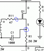
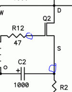
Did you measure the voltages across both R1 (0.56R) and R2 (0.47R)?
Anyway, you turn P1 to turn on Q1 and P2 to turn on Q2.
Can you measure your Vgs voltages for Q1 and Q2? (Please see position of probes in attached)
Is it possible you did not turn P1 and P2 enough to develop adequate gate to source voltages at the output mosfets to turn them on? You may need quite a few turns before anything happens.
Did you measure the voltages across both R1 (0.56R) and R2 (0.47R)?
Anyway, you turn P1 to turn on Q1 and P2 to turn on Q2.
Can you measure your Vgs voltages for Q1 and Q2? (Please see position of probes in attached)
Attachments
jm,
In addition, the way you have your pots installed (i.e. it matches the silkscreen, seen in post#58), turning them counter clockwise in my experience should increase the voltage to the gate and hence start to bias the amplifier since the MOSFETS will eventually reach their Vgs threshold (approx ~ 4V). On IRFP240’s you can place the multimeter probes at gate and source pins (as Dennis has shown in his pics) which corresponds to the side leads of the mosfet (i.e. not the center lead). Gate = Pin 1. Source = Pin 3. You have trimmed your leads flush to the PCB as such, this may be a slight challenge. Make sure your probes don’t slip, as they may create a short. Steady hands. And perhaps a 3rd hand.
Many times, newbies don’t realize how much the pots need to be turned in order to open the flood gates (!) and turn the MOSFETs “ON.”

So for starters, measure the voltage across the Gate and Source pins and report back here. Then turn the pot counterclockwise by one or two turns. See what the changes are. Do it again. And again. At some point, it should be higher than 0V. At that point, you will know that 1) you have been turning the pots in the correct direction and 2) you are starting to turn ‘on’ the MOSFET (and the MOSFET will start to get warm). If you have heard an audible ‘click’ from the pot, you have already reached the end of the pot - this shouldn’t be occurring with the requisite voltages (~6V) you have from the divider circuit.
Once your are convinced that you are turning the pot in the right direction, and the MOSFETs are warming up, switch your leads to go across R2 and perform the bias procedure as 6L6 has advised in the 1st page of this thread. Also have another DMM connected to speaker output and speaker ground so you can reduce the offset incrementally. You will notice that as you reduce the offset, the bias current will creep up a little. This is normal. It can take up to 30 minutes to completely set the bias and reduce offset to satisfaction in this amplifier.
Best,
Anand.
In addition, the way you have your pots installed (i.e. it matches the silkscreen, seen in post#58), turning them counter clockwise in my experience should increase the voltage to the gate and hence start to bias the amplifier since the MOSFETS will eventually reach their Vgs threshold (approx ~ 4V). On IRFP240’s you can place the multimeter probes at gate and source pins (as Dennis has shown in his pics) which corresponds to the side leads of the mosfet (i.e. not the center lead). Gate = Pin 1. Source = Pin 3. You have trimmed your leads flush to the PCB as such, this may be a slight challenge. Make sure your probes don’t slip, as they may create a short. Steady hands. And perhaps a 3rd hand.
Many times, newbies don’t realize how much the pots need to be turned in order to open the flood gates (!) and turn the MOSFETs “ON.”
So for starters, measure the voltage across the Gate and Source pins and report back here. Then turn the pot counterclockwise by one or two turns. See what the changes are. Do it again. And again. At some point, it should be higher than 0V. At that point, you will know that 1) you have been turning the pots in the correct direction and 2) you are starting to turn ‘on’ the MOSFET (and the MOSFET will start to get warm). If you have heard an audible ‘click’ from the pot, you have already reached the end of the pot - this shouldn’t be occurring with the requisite voltages (~6V) you have from the divider circuit.
Once your are convinced that you are turning the pot in the right direction, and the MOSFETs are warming up, switch your leads to go across R2 and perform the bias procedure as 6L6 has advised in the 1st page of this thread. Also have another DMM connected to speaker output and speaker ground so you can reduce the offset incrementally. You will notice that as you reduce the offset, the bias current will creep up a little. This is normal. It can take up to 30 minutes to completely set the bias and reduce offset to satisfaction in this amplifier.
Best,
Anand.
Last edited:
When I set the pots up on the bench initially measuring them with a dvm I found the pots were a bit counterintuitive to me at least. Initially I wanted to set them at a minimum before powering up. In trying to do so I expected there to be some sort of stop to indicate end of range. But with these pots the adjustment dial just continues nonstop. I’m not sure I’m explaining that very well but it was difficult to get the pot adjusted to zero within it’s
range. So I basically practiced getting into that range so I could set them correctly. Hope this makes sense and helps
Also these are 25 turn pots iirc and are very sensitive to any adjustments.
This was my experience but I can’t emphasize enough how much easier setting bias was after the led string change suggested above. Hopefully you will get this resolved soon.
It can be very frustrating
Best
The pots make a faint click sound when you are at the highest or the lowest point.
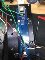
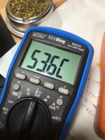
I want to thank all of you for your help. Each of you has contributed to my better understanding the bias/offset procedure for the F6. First, while I recognize that my pot is a 25 turn Bournes, I did not realize just how many turns I would have to make to get current to flow. Second, I was turning the pot clockwise when I should have been turning it counter clockwise as Dennis and Poseidonsvoice indicated. I now have 0.503 VDC bias and 0.30 mV offset. Temperature at the screw holding down the MOSFET closest to the bias pot levelled off at about 59.9 degrees C. Pictures below. On to the left channel......
Thanks to all for your excellent help,
jm
Thanks to all for your excellent help,
jm
Attachments

Cool! once you get the heatsink installed onto the chassis and verticle temp should come down a bit
- Home
- Amplifiers
- Pass Labs
- F6 build