Bonsai, my Lada goes faster than your car without wheels 😉The 7815 devices are quieter than the 317 without caps - about 150uV wide band noise vs about 350uV. Where possible, I go for 7815.
Did not look up the designer of the device but I feel politics come around when exceptions are mentioned (that to confirm the rule).
The application guidelines don’t cover every use case. There are multiple regions of instability depending on load capacitance and load current. The graphs in the data sheet only show one. And an LCLCLCLCLC distributed network doesn‘t behave as a single Equivalent C. As you add circuitry to the board, you chase a moving target. And adding a big honking 1000 uF to each rail just resulted in start up problems. The zener and pass transistor pair simply didn’t care how many .01 uF ceramic discs I had sprinkled on the board to bypass pins 4 and 8.
I’ve never seen those graphs on any of the data sheets. L’s isolate C’s at HF in distributed networks so you can end up with a pretty accurate 4 component model of the load (L, C, ESR and Rload). It’s very easy to get a handle on stability by pulsing the output load and looking at the railover/under shoot which in a well decoupled system will be some 10’s of mV above and below the nominal Vout. I’ve done that and you can see the excessive overshoot with no or inadequate decoupling. Doing it properly always solves the issue.
If you prefer discrete regs, that’s fine, but let’s not go down the ‘IC regs are problematic’ route when 100’s of millions are sold and used every year without a single issue.
YMMV 🙂
If you prefer discrete regs, that’s fine, but let’s not go down the ‘IC regs are problematic’ route when 100’s of millions are sold and used every year without a single issue.
YMMV 🙂
The 78xx can be adjusted with two resistors but I think a capacitor (less than 50uf) must be across the adjustable resistor. That is not needed with the 317 unless an improvement in regulation is needed. There is uncertainty in any regulator document I have read.It is easy to set up, just a resistor to output / input from the ground pin, so it is cheap and reliable, and consistent in production.
I think you need a preset to do that on a 317, and the total parts count (= cost) is higher in case of the 317.
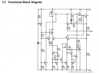
Here is a functional model of the 78xx. The ground pin does not look like an adjustment signal. Perhaps adjustment would be better with a few 914 diodes to create a fixed reference.
Attachments
Datasheets are written for professional designers. Most commercial designs are massively cost-focused, and so datasheet recommendations tend to focus on what you can get away with and still end up with a stable and usable product. What borderline neurotic audiophiles may consider "better" is very much an edge-case 🙂So TI is wary of capacitors. I think it means that if you want to produce a bunch of cheap PCBs for sale on Ebay, then don't bother with capacitors. On the other if want to DIY a few PCBs for yourself and friends, then select good capacitors for careful design.
You can set the ctage
I set =(Vrego - Vreg)/Rset This is the current flowing between the reg output and it’s ground pin; Rset is the resistor between the regulator output and it’s ground pin. Iset is the 4-6 mA figure mentioned above.
Next, calculate the resistor value required between the regulator ground pin and the system 0V
Rlower = (Vout - Vreg)/(Iset - Iq) where Vout is the desired output voltage, Iq is the data sheet ground pin current.
Raising the output of a fixed voltage reg is pretty straight forward. First, you determine the current flowing out the ground pin. This is usually 50 to 200 uA. You then set up a current between the output and ground pin of 20x to 30x this value. Typically this is 4-6 mA. You calculate the resistor from the IC ground pin to the system 0V like thisThe 78xx can be adjusted with two resistors but I think a capacitor (less than 50uf) must be across the adjustable resistor. That is not needed with the 317 unless an improvement in regulation is needed. There is uncertainty in any regulator document I have read.
Here is a functional model of the 78xx. The ground pin does not look like an adjustment signal. Perhaps adjustment would be better with a few 914 diodes to create a fixed reference.
I set =(Vrego - Vreg)/Rset This is the current flowing between the reg output and it’s ground pin; Rset is the resistor between the regulator output and it’s ground pin. Iset is the 4-6 mA figure mentioned above.
Next, calculate the resistor value required between the regulator ground pin and the system 0V
Rlower = (Vout - Vreg)/(Iset - Iq) where Vout is the desired output voltage, Iq is the data sheet ground pin current.
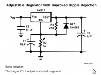
Not true, it is somewhat the other way around. 78xx normally don't have any cap across the normally non existing adjustable resistor while it is recommend with LM317 that usually has the setting resistor. LM317 datasheet clearly mentions what improves by adding the Cadj cap. Without it it makes no real sense to use LM317 over 7815. A 7 dB improvement in ripple reduction is worth the few cents for the cap. If low cost is your thing then maybe but since DIY is more expensive than ready built stuff one better aims for highest performance. Why would one aim for less good performance? Of course one wants better regulation and better ripple reduction!The 78xx can be adjusted with two resistors but I think a capacitor (less than 50uf) must be across the adjustable resistor. That is not needed with the 317 unless an improvement in regulation is needed.
It is funny to debate old school parts when low noise LDO regulators have been developed that are RF proof as well. TPS7A4700, LT3045/LT3094 and a few others turned out to be good choices. Of the dinosaurs LM723 still is very good.
Last edited:
Attached is an optional improvement. If I add the cap to reduce ripple, I must also add the protection diode. I would consider doing that if ordering a FAB pcb. If I was just hacking a breadboard, I try to keep it simple as possible.Why would one aim for less good performance? Of course one wants better regulation and better ripple reduction
Attachments
"It is funny to debate old school parts when low noise LDO regulators have been developed that are RF proof as well. TPS7A4700, LT3045/LT3094 and a few others turned out to be good choices. "
I recently bought a Schiit Loki Mini+ because I needed a tone control to reduce bass from the big speakers in my small office space. The Loki comes with a 20 watt, 16vac wall-wart that outs 19vac no-load and 18.4vac when plugged in. The big wall-wart enables using the compact case of the Loki. But the Loki runs hot, it stung my fingers when I touched the 1000uf caps. It has SMD 317-337 which heats the case to 50C or more. This happens because 18.4ac -> 23.4dc for the 317-337 to produce 15vdc. So 7.7vdc across the 317-337 which has no heatsink. I suppose the PCB is an overloaded heat spreader.
I plugged in an old 15 watt 12vac wart to the Loki which now runs 40C degrees which is 10C less than the "burning Loki". The 317-337 gets 17.5dc for 15dc out which is probably marginal. In that case, an LDO design would have been better given the difficulty of selecting a matching wall-wart.
If one desires performance on a few levels like low noise low loss low heat then modern regulators like TPS7A4700 are suitable. I had a few devices on 14V DC which I created with selected highish output 12V transformers and TPS7A4700. These ran for years without any issue. A tiny heatsink was enough. It is nice challenge to design such PSUs as one needs to calculate, measure and take mains voltage variations in account. The lower the desired output voltage is, the more difficult things become. Schottky diodes/LT4320 are a given, just like high value filter capacitors to reduce ripple.
Now the surprise was that TPS7A4700 caused the devices to sound different than when using LT3045 (which really was a little too tight with its 20V maximum input voltage). Both perform very good with LT3045 having the 20V issue and the need to parallel them for 1A.
* What you call "optional improvement" is in reality the performance you are after and leaving parts away is called "costcutting at the expense of performance". One regularly can see designs without the diode but I would add pads to be able to install it. Just like CLC and RF protection. Things can be done good and they can be done cheap. In many areas of the world apparently lowest cost is the main goal and no questions are asked. Simple experiments with DIY designs will tell otherwise. Beware! Once you are into this you will notice many devices benefit from a good PSU. You will also meet 3 not so nice chaps which are Cost expressed in $ or Euro, Time expressed in hours and Effort expressed in BST.
Again: Volts, Ampères, Watt, µF. Respect for those that were the founders of all we now have. Writing stuff correctly makes one look smarter as well.
Last edited:
One obvious reason to use 78xx/79xx is the 3 pin simplicity with very few extra components and a varity of housings which are all easy to hand solder through hole as well as smd, and for a lot of applications I think they are a good choice.
This is almost the same for LM317, but a little more components needed .... the same is not true for newer (and better performing) devices like TPS7A4700.
I would call myself a DIY'er and I have both 78xx and LM317 in the drawer.
If you want adjustable, then of course it makes sense to use LM317, but in a hurry LM78xx will do 😉
Yes, "will do" is the enemy of "high performance". It is about what one desires but a chain really is as strong as its weakest link.
Fubar3, please take into account that ripple voltage can be a determining factor. Just suppose the ripple voltage is some Volts (a 1000 µF cap....) and the minimum dropout voltage margins of the regulator are breached regularly.
Fubar3, please take into account that ripple voltage can be a determining factor. Just suppose the ripple voltage is some Volts (a 1000 µF cap....) and the minimum dropout voltage margins of the regulator are breached regularly.
Last edited:
Actually less parts are needed for a 7815 if you use it as a 15V regulator. Say you have a design where you need a 15V rail and a 17V rail. Use two 7815s and two resistors on the one making 17V.What parts? What complexity? The procedure and parts required for the LM317 are identical to that for the 7815. Only the values are different.
If you used 317s you'd need four resistors. If you used a 7815 for the 15V and a 317 for the 17V then you're increasing the number of unique components in your design which slows down or complicates manufacturing.
Wow, impressive part count 😀
If one has opened higher quality devices the past decades one saw more 317/337 (and those 4 resistors and 2 caps) than 78xx except of course for 5V use.
That Whammy must be by a “name” otherwise this discussion is pretty pointless. If it is by Pass, well I think he used 317/337 in a DAC so these must be excellent/class A/H2 and H3 enhancing etc. I am out, have fun!
Last edited:
Obviously, but that's not the topic of the thread.Actually less parts are needed for a 7815 if you use it as a 15V regulator.
I've read and noticed over the years/decades that negative regulators are not as good as positive regulators. I've also noticed that many/most low-voltage-output power transformers have two separate output windings rather than a single center-tapped winding. This takes only one more connection to the transformer and makes it much more versatile, windings can be in series for traditional +/- supply circuits, or in parallel for a single higher-current output, or ...The problem was the local bypassing sprinkled all over the board to keep the op amps stable and not talking to one another over the power supply lines messed with the negative regulator. Zener diode and pass transistor to the rescue. No feedback, no oscillate. Just one little 2 ohm base stopper and it’s unconditionally stable. And starts up properly, every time with no tricks or finagling required.
The 337 may be the worst of the bunch. Try using one for a -Vg supply for a depletion mode RF power FET and see what kind of trouble you run into. KHz oscillations, latch up - and total loss of regulation when the power FET goes into rectification (positive gate current). Those RF power devices cost more than 44 LF353’s too, and just as dead.
Combining these facts, one can make a +/- supply out of two identical positive regulators, use an extra bridge rectifier so each regulator circuit is fed from its own winding, then connect the supplies at their outputs, one negative output to the other's positive output. This makes for a single regulator design for both + and - outputs. Or you can use discrete parts if a zener/emitter follower works for you. Regardless, you can be sure the + and - supplies have the same performance, the "best regulator you can make/buy."
then why did you even respond to that commentObviously, but that's not the topic of the thread.
Because it was incorrect?then why did you even respond to that comment
Alas, the thread is drifting .. they all do eventually. I have decided that the concept of connecting a fixed regulator ground to a reference voltage to lift the output was an accidental feature, not by intention. It may have undiscovered flaws unless it is integrated with an opamp as shown in app examples.

- Home
- Amplifiers
- Solid State
- Why adjust 7815, a fixed-voltage regulator?