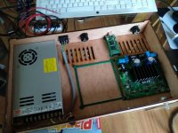
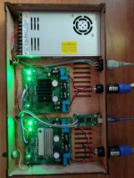
I have completed my "boxing" to drive my LX-Mini:
- one LRS-350-36V power supply for both modules,
- 2 NeatAmp Modules for Left - Right,
- Volume pot controlled by the uC to drive both TAS3251 modules
- Asynch USB to I2S modile with a good clock
- laser cut plywood case designed on purpose,
- 3D printed stands for the 3 PCBs,
- Speakon connectors.
High performance open hardware for active speakers in a small package. No compromize on the components quality.
With the included DSP, I will be able to fine tune the speakers freq response, and time alignment.
Embedded uC allows various features and HMI.
Works wonderfull 🙂
JMF
Attachments
Hi,
Congrats Jean-Marc, this is very DIY.
Laser cut wood box is impressive and custom stands for the boards are a very nice touch !
Happy you enjoy the result !
Chris
Congrats Jean-Marc, this is very DIY.
Laser cut wood box is impressive and custom stands for the boards are a very nice touch !
Happy you enjoy the result !
Chris
Hello AIM65,
I have a short question on your code for the TAS3251. The DSP can't be initialized if there is no clock on the I2S. Do you check during the startup sequence the the DSP part of the TAS3251 is "alive" ?
Up to now, I always power the Amp board with the USB to IS2 board and I don't had issues. But this looks like a possible case.
JMF
Hi,
Some sources provide I2S signal as they’re powered, other not.
On my test software I do not manage this, as the software is mostly intended to develop and tune uses case.
On my preamp project, the NeatAMP board is I2S fed by the preamp. Each time there’s a change in the source selected by the preamp (error / change source), the preamp shut off the TAS, wait source to get ready , then reinit the TAS with the right parameters, this guarantee a proper startup. The preamp is equipped with an Uc which speak to NeatAMP’s Uc though a basic serial protocol, that’s the Preamp Uc which decide whereas the signal is correct or not, not the NeatAMP Uc which is basically slaved to the preamp.
If you want NeatAMP’s Uc to handle this duty you can use the status registers to monitor when PLL is locked then reinit the TAS. Upon error detection I believe TAS goes automatically to mute or provide you some help to catch the error and stop it.
Chris
Hello
I finally found the time to post some information on my preamp for NeatAMP project. They are in the following thread:
NeatAMP Pre : a digital preamp for NeatAMP
Chris
I finally found the time to post some information on my preamp for NeatAMP project. They are in the following thread:
NeatAMP Pre : a digital preamp for NeatAMP
Chris
Hello
power supply test passed ok, C8 are populated but the TAS are not here yet. There is manufacturing problems and no restocking date. So wait and see not too long I hope.
Séb.
power supply test passed ok, C8 are populated but the TAS are not here yet. There is manufacturing problems and no restocking date. So wait and see not too long I hope.
Séb.
Hi Seb,
I hope that you won't fall in that chip shortage trap. Seems that there more and more tension in the market.
JMF
I hope that you won't fall in that chip shortage trap. Seems that there more and more tension in the market.
JMF
this is such a cool project. I am trying to learn more about bit streaming audio from something like a Raspberry pi over I2S to TAS3251. Does that part require any middleware or kernel modifications?
Thanks! Also, look forward to sampling the end product if you end up commercializing it 🙂
Thanks! Also, look forward to sampling the end product if you end up commercializing it 🙂
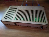
I have completed my "boxing" [...]
I don't like the case - but that's of course just my personal taste. What's not a matter of taste or preference is, it's not shielded and the extremely long slots weaken the plywood, a single point pressure can break them fairly easily. If you leave material in the middle it becomes much stronger or even make it 3 smaller slots, it gets a lot stronger. The slots also are very inviting for things to fall in and these can be quite large.
The case doesn't have any shielding (except the PS), the air intake slots on one side of the PS is blocked, the low voltage wires go over the AC input contacts and the power switch and -cables. Also, the AC cables aren't secured secured, which means they can go out of the case, get caught by something and ripped out, even if the chance to that happening is very slim. All of the plugs are just mounted by small wood or tin screws, which can be pulled out easily, that can easily happen with the locking Speakon plugs, the cables can then make contact with the AC input.
That could easily be avoided by placing the Power input and the switch and its cables to the left side (much better visually too, but that's ofc just my taste) and turning the PS 180°. The can be much safer mounted if you use M screws, washers and the nuts secured with Loctite, superglue etc. The best thing of it is, the improvements are extremely cheap (except for the shielding).
Hello everyone!
I have designed my own module using the TAS3251 and I'm having issues which I haven't been so far able to resolve.
When I run the module on lower frequencies (the subwoofer range approx. 40-120 Hz) there is a sort of clicking noise occuring which increase with power level. On low power levels, it is inaudible but when I run the subwoofer on full power, it ruins all the sound.
I doubt this is an analog noise. It sounds more like that something is "switching" and it depends on the current which I draw from the outputs.
The setup I am using is this own module with TAS3251 connected as a slave to the TAS3251EVM board. It forms a 2.1 system where the eval board drives the stereo speakers while my own module drives the subwoofer. The subwoofer has two coils, each connected to one of the TAS3251 outputs.
The issue only occurs on my own board. The TI's eval board works just fine under all circumstances (even if I use it to drive the subwoofer).
I am quite hopeless in finding out what could be causing this problem. I would like to design a revised layout, as there may be the issues. But before I do so, I really would like to know what I am doing and where the problem is.
So far I ruled out the following:
I believe there is a chance someone ran into similiar problem with any different class D amp, so perhaps anyone got a clue what is behind this issue?
I'm attaching some files: photo of the TAS3251 module, wideo with the issue recorded, PDF schematic and EAGLE design files
By the way this project is solely hobby thing and not commercial.

I have designed my own module using the TAS3251 and I'm having issues which I haven't been so far able to resolve.
When I run the module on lower frequencies (the subwoofer range approx. 40-120 Hz) there is a sort of clicking noise occuring which increase with power level. On low power levels, it is inaudible but when I run the subwoofer on full power, it ruins all the sound.
I doubt this is an analog noise. It sounds more like that something is "switching" and it depends on the current which I draw from the outputs.
The setup I am using is this own module with TAS3251 connected as a slave to the TAS3251EVM board. It forms a 2.1 system where the eval board drives the stereo speakers while my own module drives the subwoofer. The subwoofer has two coils, each connected to one of the TAS3251 outputs.
The issue only occurs on my own board. The TI's eval board works just fine under all circumstances (even if I use it to drive the subwoofer).
I am quite hopeless in finding out what could be causing this problem. I would like to design a revised layout, as there may be the issues. But before I do so, I really would like to know what I am doing and where the problem is.
So far I ruled out the following:
- Wrong configuration of the TAS3251 chips. I use the TI's PPC app to configure both. There is absolutely no way how to remove/reduce this issue by any settings.
- Fake TAS3251 chip. I had to buy one of them on Aliexpress due to the chip shortage. I originally though this may cause the problem, but eventually I soldered this Ali chip on the original TI's eval board and there it works just fine.
- Power supply issues. I removed the 12V and 3V3 power circuitry from the board and connected these supply rails directly to bench PSU. No change in this issue.
- Wrong component use. All the components are according to the datasheet (or better)
- Wrong circuit design. I basically used the same circuitry as the eval board uses. There is nothing I have added or changed.
- PCB layout. I followed all the reccomendation from the TAS3251 datasheet, including the placement of critical components (decoupling caps etc).
I believe there is a chance someone ran into similiar problem with any different class D amp, so perhaps anyone got a clue what is behind this issue?
I'm attaching some files: photo of the TAS3251 module, wideo with the issue recorded, PDF schematic and EAGLE design files
By the way this project is solely hobby thing and not commercial.
Attachments

Thanks for the hint. This is something I did not check and neither I was aware of this phenomenon. Seems like I have work to do tommorow.PSU rail pumping?
//
If this is the cause, I'm still curious though why only the one board (my own design) exhibits the issue and not the other one (TI's original eval board) while both are connected to the same PSU (even if I swap them, so the TI board drives the subwoofer).
Just in case anyone here tried to program the TAS3251 by writing the I2C registers manually - in what register I can select which process flow I want to use?
Have you tried your board without EVM, with a basic initialization sequence ?
In order to understand the issue, does the click on the video appears when you are changing the volume ? or do you hear them when volume is high ?
Following TNT advice can you monitor the quality of the negative voltage generated by the charge pump : CPVSS on pin5 which should be connected to 1uF MLCC. Are they any glitch related to your 'clicks'
PCB picture shows you're running in slaved clock mode (output stage clock, not I2S). Are clock inputs well connected to the master on EVM, have you tried running with local clock ?
Last edited:
You do no select process flow through single register setting. it's a global config per process flow and there are some undocumented register.Just in case anyone here tried to program the TAS3251 by writing the I2C registers manually - in what register I can select which process flow I want to use?
Back to the pcb picture :

External oscillator (OSC IOP et OSC IOM) are not connected, but mode is slave, that should cause a clock issue. Does your current setup have the same configuration as the one of this picture ?
For clock operation, read TAS3251 datasheet page 40 & 41.
Chris
External oscillator (OSC IOP et OSC IOM) are not connected, but mode is slave, that should cause a clock issue. Does your current setup have the same configuration as the one of this picture ?
For clock operation, read TAS3251 datasheet page 40 & 41.
Chris
Last edited:
Sorry to mislead, but the TAS3251 is actually running in master mode. The picture is only taken at bad angle. There are 4 positions of the jumper switch (same as on EVM) and I use the 2nd position.Back to the pcb picture : View attachment 1108174
External oscillator (OSC IOP et OSC IOM) are not connected, but mode is slave, that should cause a clock issue. Does your current setup have the same configuration as the one of this picture ?
For clock operation, read TAS3251 datasheet page 40 & 41.
Chris
To your other points:
- I can run the board without EVM. I designed a control module with ATMEGA32 which I use to fetch the init data (generated from PPC) over I2C. I can also run the TAS3251 just by enabling the normal operation mode. But all of these scenarios have no impact on the bass clicking issue.
- The click sound defect is directly proportional to the volume level - the louder the output, the more significant the deffect appears. It seems that the actual change in volume does not cause any problems.
- I tried some troubleshooting relevant to the proposed PSU rail pumping. I used a linear bench power supply instead of a switching one, and connected some large caps to the PVDD rail close to the chip. This did not affect the defect in any way.
- I did not try to monitor the negative voltage generated by the charge pumps. That would be probably the next step I'm going to do. Thanks!
Also - in my original post. I said I run the board in slave mode. This was incorrect. Both boards are running in master mode and the only difference in configuration of them is I2C address. They take the same I2S input and if I run the my-own board standalone, there is no change in the bass clicking issue.
About the click sound, which signal is there on input when it occurs ? is there some music or a silence ? Could you try to ground data, then mck, then lrck. Depending on the config the TAS could run in 3 or 4 wires mode : with or without MCK.
In order to locate the cause, you could try to remove C25 and C26. As a result, you will know if the issue is on the DIR-DSP-DAC side or on the Class D amp side. TAS3251 is a multi die chip.
What do you means by "I can also run the TAS3251 just by enabling the normal operation mode" ?
I encounter some weird and unpredictable behaviors trying to manage the chip with I2C running @400kHz. Which is your I2C speed ?, if 400 switch back to 100.
Hope this help...
- Home
- Amplifiers
- Class D
- [design log] Neat 2x170W I2S in, I2C controlled, integrated DSP amp (TAS3251)