Also, there's usually a tone control in the circuit, a capacitor valued to roll off at maybe 1k or 2k (Hz) when directly across the pickup, in series with another 250k (ohms) pot, thus at higher frequencies the pickup sees 125k ohms.Not sure if the waveforms can be compared to the real world data.
There is a 250 k volume control connected to the pickup directly. Is the waveform measured in the scope with this pot in circuit?
Furthermore, there's the guitar cable capacitance, usually several hundred pF and dependent on the cable's capacitance-per-foot and length. Guitarists complain about cables sounding different, and the difference in capacitance is probably 99 percent of the difference.
Further complicating things, the capacitance doesn't JUST dull the tone (as it's in parallel with the pickup winding resistance, around 6k to 15k), but it also causes a resonance with the pickup's inductance, adding a broad peak in the response, often around 5kHz.
Some guitars have "active pickups," active electronics that buffer the pickups so they see a very high impedance, but then some may complain it "sounds too bright" or too plain. What's more, it insulates the pickup from the cable capacitance and thus gets rid of the broad peak resonance.
Getting a "good" guitar tone from a pickup requires the right amount of resistive and capacitive loading, but guitarists have little control over this, mostly because they don't understand exactly how volume and tone controls, cable, and amp input impedance affect tone.
Indeed, or it may be exactly what you want for a staring point. A direct scope connection shows the Thevenin equivalent voltage from the pickup, then you can send that through some r/l/c circuitry or spice simulation to see what comes out.Scopes usually have 10 meg input impedance. If the pickup is directly connected to scope, there is almost no loading. The waveforms may be misleading.
There are many layers of EQ in a guitar signal chain. There's EQ (tone controls, pickup position, pickup inductance) inside the guitar. There is (electrical) EQ in the preamp and tone controls. In some vintage Fender amps there is still more EQ in the stage that mixes reverb and direct signals.Yup, but Guitar amp preamp circuits already have that EQ curve buried in its circuit and Tone controls?
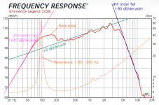
On top of all this, speakers designed for use in guitar amps do not have a flat frequency response - not even close. I added the coloured lines and annotations to the frequency response of an Eminence Legend 1028 in the attached image. You can see that there is all sorts of EQ going on - deep bass roll-off, a bass boost around 150 Hz, a dip around 300 Hz, gentle treble boost from 500 Hz to 3 kHz, and finally a very steep treble cut above that.
That means there is also a lot of additional EQ in a guitar amp [/i]loudspeaker[/i]. That's why swapping speakers can change the sound of an guitar amplifier a lot.
Changing from voltage drive to current drive makes a big difference to the EQ curve of the guitar loudspeaker. Higher driving impedance adds treble boost, and also a bass hump around the speaker resonance.
It's likely that those primitive open-back loudspeaker enclosures from the early days of tube audio helped to hide the soggy, poorly damped bass hump resulting from high-Z drive.
-Gnobuddy
Attachments
You can't equalize away the poorly damped fundamental resonance and soggy bass.True, but you can equalize that out with a filter.
I've measured far more THD from a woofer at low frequencies than at high frequencies. Peak excursions fall rapidly as you go up in frequency. There's lots of THD when the excursion is large, at low frequencies.
For Hi-Fi, I'm not a fan of constant current drive to the speaker. And that's putting it very mildly. 😀
-Gnobuddy
Yes, it is. Elliott didn't modify his guitars for the measurements.Not sure if the waveforms can be compared to the real world data.
There is a 250 k volume control connected to the pickup directly. Is the waveform measured in the scope with this pot in circuit?
Earlier in this thread, I posted the link to Rod Elliott's page, from which this waveform came. He describes his test procedure in plenty of detail.
Not every guitar uses a 250k pot. Most of my guitars have a 470k or 500k pot, which is typical for guitars with humbucker pickups.
A 500k pot set to half-resistance has an output (Thevenin) impedance of 125k all by itself, even if the pickup itself had zero impedance of its own.
In real life the pickup adds additional output impedance on top of this. So a typical humbucker-equipped guitar can have an output impedance of well over 125k.
Feeding this into a 220k input resistance immediately wastes one-third of the signal (lost in the 125k/220k voltage divider). It seems like a poor move that will only worsen the signal to noise ratio of the amplifier.

Low input impedance rolls off treble (acts as a low-pass filter) in conjunction with the pickups inductive series impedance.Manufacturers like Peavey, use 220 k input resistors which may actually remove some harsh spikes.
That low 220k input impedance will kill "shimmering" high treble frequencies, which isn't good for guitarists who want good clean tones.
Interestingly, manufacturers like Peavey are most well known for very highly distorted guitar sounds - which IMO are barely tolerable even after filtering out all the higher treble frequencies. Famous Peavey amps are not known for "glassy" clean treble, like vintage Fender tube amps.
In fact the most famous Peavey (5150) has terrible clean tones...but the people who love those amps are not interested in clean tone at all, so the amp works fine for their purposes.
Low input impedance rolls off treble (a low-pass filter) in conjunction with the pickups inductive series impedance.Earlier Jazz chorus amps had even lower input impedance.
You get less high end when you feed a guitar into a lower resistance.
Jazz is an old genre that typically uses very muted guitar tones - treble is very heavily rolled off. Think George Benson, for instance in his 1976 piece "Breezin":
(You have to wait through nearly 90 seconds of schmalzy pop-music sounds before you hear Benson play a note.)
Maybe Roland wanted their amp to make those typical muted jazzy noises that jazz guitarists of that era wanted.
Maybe the treble roll-off from too-low input Z helped them conceal solid-state harshness.
The JFET circuitry in the early Jazz Chorus was surely a big factor in keeping away solid-state harshness.
I don't know enough about these amplifiers to be sure ( I think you know a lot more about them than I do.)
I do know that Roland/Boss had a pool of very talented engineers, and they obviously took/take their design process seriously. They made (and still make) a lot of good-sounding guitar electronics. Their Boss Katana series were the first affordable solid-state guitar amplifiers I've ever heard that could sound quite convincingly "tubey" when set for clean tone.
Before the Katana, you had to shell out a grand or more to get a decent-sounding solid state guitar amplifier (Kemper, AxeFx, etc). Not really a viable proposition for a hobby musician like me. I play music for love, not for money. (The root of the word "amateur" is "amore", i.e. "love"!)
Try it with a low-output single coil in the bridge of a 'Strat, and a guitar amplifier with extended treble response. See what your ears say. (My ears don't agree with Elliott.)Rod Elliot somewhere said, there will not be any sound difference unless the input impedance goes below 68 k.
IMO it does reduce harshness, but at the unacceptable cost of also rolling off the sparkly high treble frequencies that give a lot of life to clean guitar tone, particularly with single-coil pickups.I believe lower impedance might affect the sustain of the sound but improve over the harshness..
I can't think of a good reason why low input Z would affect guitar sustain - but I'm willing to be convinced if someone can produce actual measured data to prove this.
-Gnobuddy
You can't equalize away the poorly damped fundamental resonance and soggy bass.
Why not? A biquad or two should do the trick, shouldn't it? The trick is to get and keep them properly tuned, of course. You will have some low-level resonance left when the zeros of the filter are not exactly at the poles of the loudspeaker, which they never are in real life, is that your concern?
A more elegant approach is combining current drive with motional feedback. A third and quite old approach is acoustic damping.
Last edited:
I've never been attracted to "lipstick on a pig". Cone suspensions soften with temperature rises, stiffen with age. How long before the lipstick, sorry, biquad is far off-tune?Why not? A biquad or two should do the trick, shouldn't they?
And how much extra output power does the amplifier need, to provide the amount of mechanical damping you'd get for free if you simply drove the speaker with constant voltage, the way god and all her angels intended?
And more importantly, Rice and Kellogg, and all the subsequent engineers who perfected their invention, intended? 🙂
IMO, much better to start with a mechanically well-behaved system, and only use lipstick for subtle fine-tuning of an already much less piggy system. That means driving the speaker with a low source impedance so voice coil back-EMF can do what it's supposed to do.
From what I saw, once you have a decent amount of motional feedback, the actual driving impedance becomes more or less irrelevant. The amplifier will put out whatever signal is necessary to make the speaker voice coil Do The Right Thing (TM). Within reason, of course.A more elegant approach is combining current drive with motional feedback.
Drive impedance is only important in normal speaker systems because speakers are open loop devices, and the amplifier doesn't "know" exactly what the speaker diaphragms are doing. The moving parts of the speaker just follow Newton's laws of motion, with Lenz' law thrown in for the electromagnetic damping.
I was extremely impressed with the performance improvements I saw from MFB on the prototype I built and measured. Those were far and away the biggest improvements I've ever seen to any kind of low-frequency loudspeaker driver. Such a pity MFB never really made it to mass production, other than a handful of boutique products.
DIY MFB would be much easier today, as tiny cheap accelerometers are readily available. Back in 1998 I had to build my own accelerometer out of a piezo-ceramic buzzer disc. Getting enough bandwidth out of the accelerometer was a challenge in itself.
Back on topic, we don't want MFB on a guitar speaker. As JM Fahey once put it, a guitar amplifier is really a signal processing device, not a (linear) amplifier. And a guitar speaker is an EQ device, not a (flat-response, linear) loudspeaker.
-Gnobuddy
And its EQ response curve depends heavily on the output impedance of the amplifier driving it, especially near its resonant frequency.And a guitar speaker is an EQ device, not a (flat-response, linear) loudspeaker.
I think I heard more difference in the treble range than the bass (maybe because of poor bass response of an open-back cab?)
If I'm reading the attached graph correctly, it looks like the impedance of an Eminence Legend 1028 climbs from around 6 ohms at 300 Hz all the way to nearly 15 ohms at 3 kHz.
If fed from a current source, that means speaker terminal voltage climbs by 8 dB from 300 Hz to 3 KHz.
The slope is "only" about 8 dB per decade, but still - 8 dB is a lot of treble boost!
Put another way, if fed from a constant voltage source instead, voice coil current would drop 8 dB between 300 Hz and 3 KHz, causing a significant amount of treble droop.
When I tried to use an L-pad as a speaker attenuator with a tube amp, it was the duller treble response that I noticed.
-Gnobuddy
Attachments
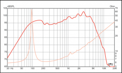
Yes, and the impedance at 95Hz (Fs, free-air resonance) is 70 ohms.If I'm reading the attached graph correctly, it looks like the impedance of an Eminence Legend 1028 climbs from around 6 ohms at 300 Hz all the way to nearly 15 ohms at 3 kHz.
The response chart uses a constant 2.83 volts, "one watt" into a nominally 8 ohm speaker. The rising on-axis response is what you would hear from a constant voltage source. Off axis, the upper response would drop.Put another way, if fed from a constant voltage source instead, voice coil current would drop 8 dB between 300 Hz and 3 KHz, causing a significant amount of treble droop.
You may be noticing the reduced harmonics from driving the speaker within it's linear range, that is, under Xmax.When I tried to use an L-pad as a speaker attenuator with a tube amp, it was the duller treble response that I noticed.
Guitar speakers are often designed with low Xmax so they distort above relatively low drive levels.
The Legend 1028 has only 2.1mm Xmax, driven past that, it will produce progressively more harmonic distortion, which adds "brightness". Knock down the level by 6dB, excursion falls in half-at 1mm the speaker may have almost no distortion.
As an example, a single sine wave tone at 82 Hz, the low E fundamental note on a guitar, was sent at various voltage levels 2 to 5.66, equivalent to 1 to 8 watts (a 9 dB range) to a four ohm Epiphone 8” speaker, standard issue in the Valve Jr. combo “5 watt” amp. I’ll use watts for clarity, though without knowing the actual speaker impedance, just relative terms.
Measured at one meter, 1 watt, the second harmonic is about 22 dB down from the 89 dB fundamental, around 8% distortion. At 2 watts, up to around 11% distortion, still relatively “clean” for electric guitar. At 4 watts, the third harmonic now has risen above the second, more “edge”, though THD is still under 14%. At 8 watts, the distortion reaches around 32%, with upper third, fourth and fifth harmonics rising. About twice as “loud” sounding (+9dB) but tripling the distortion increases the perceived loudness considerably over what the the SPL (Sound pressure level) alone would indicate.
The 8” speaker used in the Fender Vibro Champ XD, also a tube combo “5 watt” amp, has nearly 100% THD driven at 8 watts, the third harmonic only 2 dB down from the 82 Hz fundamental.
Odd order harmonics are more audible than even.
Of interest, the resulting distortion from that drive level creates a full “E major” chord from the single E tone- E,B and G# notes appear in the harmonic sequence.
To be clear, the power amp used in the above tests added no measurable distortion itself.
At any rate, only a portion of the distortion or tone we associate with "overdrive" or clipping is from the amplifier.
Art
Last edited:

Indeed. Hence my comment about the open-back cab. I didn't hear the extremely woofy/pillowy bass you'd expect to hear with an enormous high-Q peak at 95 Hz.Yes, and the impedance at 95Hz (Fs, free-air resonance) is 70 ohms.
Speaking of high Q, if you drive a speaker with a constant current source instead of a constant voltage source, Q of the fundamental resonance rises from Qts all the way to Qms - which may be ten times bigger. Instead of controlled bass, you get an enormously soggy one-note bass response. (Which may be why open-back cabs were popular - they helped supress the audibility of the bass peak.)
Very interesting plots, thank you!You may be noticing the reduced harmonics from driving the speaker within it's linear range, that is, under Xmax.
I heard the effect at low power (with and without attenuator) as well.
Once I figured out the cause, I designed a different type of speaker attenuator. This version consists of a 10-ohm rheostat wired to the amplifier output, and a 39 ohm resistor in series between rheostat wiper and speaker. Output impedance never drops below 39 ohms; input impedance is near enough to 8 ohms at all rheostat settings, keeping the output tubes happy.
I no longer hear the same treble loss when using this attenuator. Raising the output impedance (using that series 39 ohm resistance) seems to have done the trick.
Speakers tend to be most nonlinear where cone excursion is highest, i.e. at the lowest frequencies. What I was hearing was happening in the higher octaves, so I don't think speaker cone excursion was the cause.
When driven with constant voltage, power = voltage^2/R. Power to the speaker falls as speaker impedance rises.
When driven with constant current, power = current^2 x R. Power to the speaker rises as speaker impedance, all else being the same.
So, when driven from a constant current source, the treble frequency response of a speaker is boosted as a result of rising speaker impedance* due to voice coil inductance.
*There are additional complexities involving power factor and so on; to be sure, I think we need actual acoustic frequency response measurements made in front of a guitar speaker, driven first with a CV source, then a CI one.
I understand and agree with your point about on-axis vs off-axis - but that is a separate issue. Changing the driving impedance changes the treble frequency response, whether on or off axis.
I've heard this opinion from guitarists many times, and of course guitar amp speaker swaps often change overdriven tone substantially. Which substantiates the opinion....only a portion of the distortion or tone we associate with "overdrive" or clipping is from the amplifier.
But your measurements are the first objective data I've seen to support these subjective claims. Excellent work!
-Gnobuddy
Really interesting!The 8” speaker used in the Fender Vibro Champ XD, also a tube combo “5 watt” amp, has nearly 100% THD driven at 8 watts, the third harmonic only 2 dB down from the 82 Hz fundamental.
My first tube amp (hybrid, actually) was a Super Champ XD, big brother to the Vibro Champ XD.
The SCXD is basically the entire power-amp section of a Princeton Reverb, with a solid state analogue / digital front end slapped down in front of it. It has a bigger cab, and a bigger and beefier 10" speaker. Push-pull 6V6 outputs, driven by a 12AX7 configured as driver and cathodyne PI.
I am that rarest of rare electric guitarists, who thinks electric guitars are usually much too loud. I've only turned up my SCXD loud enough to hear any speaker distortion once or twice in the twelve years I've owned it.
Most of the other guys I know who bought one, immediately put in an even more sensitive (read: louder) aftermarket speaker.
I briefly owned a Frontman 25R. It had a marginal speaker that would easily buzz if pushed a little. Whatever speaker distortion there was, it wasn't enough to save the amplifier from having nasty thin clean tones, and nasty buzzy overdriven tones.
-Gnobuddy
Under small signal conditions, the response under current drive is exactly the impedance of the loudspeaker times the response under voltage drive, and the response under voltage drive is exactly the admittance of the loudspeaker times the response under current drive. No need to account for power factors, as the phase difference between current and voltage is determined by the loudspeaker, independent of the driving impedance.
That's true for the voltage across the voice coil, sure. But does that translate exactly to acoustic SPL from the speaker, too? I'm not sure of that.Under small signal conditions, the response under current drive is exactly the impedance of the loudspeaker times the response under voltage drive
A loudspeaker is a type of electric motor, and these behave rather oddly compared to resistors.
A DC motor has a DC resistance - but power dissipated in the resistance does not produce rotational motion at the shaft. It only produces heat in the windings.
The motor windings also have static inductance, which you can measure if the motor is prevented from rotating. That part of the inductive reactance is wattless (no power dissipation because of the power factor.) And it doesn't contribute to mechanical output power at the shaft.
On the other hand, there is a "reactive" part of the motor impedance - the result of Lenz' law acting on the rotating windings producing back EMF proportional to RPM - which is not watt-less like a proper inductance. This reactive impedance is actually the part that represents output power at the shaft.
What of a moving-coil loudspeaker? I think a lot of the above applies. Power dissipated in the DC resistance doesn't generate any SPL, only heat. The actual voice coil inductance (with the voice coil immobilized and not allowed to move) is probably wattless. But once the cone is moving, there will be an additional apparent inductive reactance which really does correlate with mechanical power fed to the speaker cone.
So, when changing from CV to CI drive, I'm not sure that the actual acoustic power from a speaker will reflect exactly the same change in frequency response as the voltage across the speaker terminals.
I'm fighting with brain-fog today, and can't seem to think my way through this with any clarity.
On the plus side, somewhere on my PC is a Python program I wrote a few years ago, which models the mechanical and electrical behaviour of a loudspeaker driver. That can probably give me some answers.
-Gnobuddy
It's basically the substitution theorem, which applies to any network with only one solution: you can replace a part of the network with something else having the same terminal voltages without changing the solution of the rest of the network.
That is, the loudspeaker doesn't know how the voltage across its terminals (/ current through its voice coil) got there, whether it was caused by an amplifier with a current output, voltage output or something in between.
That is, the loudspeaker doesn't know how the voltage across its terminals (/ current through its voice coil) got there, whether it was caused by an amplifier with a current output, voltage output or something in between.
That makes total sense. Thank you!That is, the loudspeaker doesn't know how the voltage across its terminals (/ current through its voice coil) got there, whether it was caused by an amplifier with a current output, voltage output or something in between.
(I think I knew that yesterday (hinted at in a previous post on this thread). But today the brain-fog has really kicked in. Any minute now I might start believing the Flat Earthers.

-Gnobuddy
Agreed: the (first order) difference is in the amplifier's response to the way the speakers impedance changes at different frequencies.It's basically the substitution theorem, which applies to any network with only one solution: you can replace a part of the network with something else having the same terminal voltages without changing the solution of the rest of the network.
That is, the loudspeaker doesn't know how the voltage across its terminals (/ current through its voice coil) got there, whether it was caused by an amplifier with a current output, voltage output or something in between.
An amplifier that converts an input signal into amps will put less power into four ohms than eight. One that converts a signal to volts will put more power into four ohms than eight.
Now, given that a "voltage" amplifier has a non-zero output resistance it will have an I+Z equivalent circuit. But as the output resistance => 0 the I gets very, very large. And doesn't exist outside the mathematical model.
P.s. great sympathy with the brain fog. I've been having recurrent doses of this (and doses of fatigue) all year. Can't imagine what living with it daily, for years, would be like.
Thank you. It's pretty hellish. So sorry to hear you're dealing with this, too. 🙁P.s. great sympathy with the brain fog...and doses of fatigue...
For a couple of years I've been wondering about the cause of the dramatic labour shortages we're seeing in every profession. COVID has been a brutal killer, yet worldwide statistics are that less than one person in a thousand has died of COVID (an estimated 6.6 million dead, out of a world population approaching 8 billion).
0.1% of the labour force having died of COVID isn't enough to explain the labour shortages we're seeing. Not by a long shot.
Other explanations we've been offered are equally problematic. One explanation is that everyone gave up and retired - but there's no explanation how they're able to live without any income. Another explanation is that everyone moved to higher paying jobs - but I can't seem to find any of these mysterious higher-paying jobs out there.
Then I read a recent report which found that 21% of Canadians who've had COVID end up with "long COVID", including debilitating symptoms like chronic fatigue, brain-fog, depression, body pain, and worse. One out of every five! That is a heck of a lot worse than I had ever imagined.
It's also been estimated that over 80% of Canadians have had COVID by now (based on antibodies found in blood samples collected by labs working for our national health system).
Put those two numbers together, and that means 16% of the population has "long COVID". (21% of 80% is approximately 16%).
Now, that is a number big enough to have a dramatic impact on workplace productivity. Sixteen percent is roughly one out of every six (or seven) employees. If that many employees are unable to work (or unable to work properly) because of brain fog, fatigue, chronic pain, et cetera, no wonder employers are struggling with labour shortages.
There's the whole question of exactly how "brain-fog" is actually caused. Is blood flow to parts of the brain shutting down? Is there so little dissolved oxygen in the blood that the brain shuts partially down? And what are the long-term implications of this? Will we all remain permanently dumber than we used to be, pre-pandemic?
-Gnobuddy
On a different thread, diyAudio user Shanx referred to a solid-state guitar amplifier made by Traynor, the Bloc 100G. He also posted a link to a schematic.
That amplifier uses interesting compound gain stages, each made up of a direct-coupled n-channel JFET and a PNP BJT. Both DC and AC negative feedback are used, the DC feedback setting the quiescent operating point, while the AC feedback sets closed-loop gain.
I used the LTSpice simulated guitar signal from post # of this thread, and fed it into a (simulated) JFET-BJT stage like the ones in the Traynor.
The attached screenshot shows the result. The JFET/BJT pair gently squashes big negative signal peaks (red trace). The blue trace is the input from the guitar.
I've scaled the red trace (using R5/R6) so that it exactly overlays the blue trace if you feed the JFET/BJT pair a very small signal, such as 1mV peak. As the signal amplitude gets bigger, the JFET "squashes" the signal progressively more and more. So for big input signals, the output no longer exactly overlays the input.
-Gnobuddy
Attachments
Gnobuddy, not sure if you have the time, but have you done a spectrum analysis on the sim, at various input signal levels? What I like about this circuit stage is the gradual progression of low order harmonic distortion. At least that is what I reckon is happening from listening to that amp. And comparing to an op amp (using some kind of diode hard clipping scheme for distortion effect) if the op amp clips or the diodes hard clip, there you have harsh THD ''splatter'' all the way up the spectrum.So for big input signals, the output no longer exactly overlays the input.
Is the squashed area down about 10%? Might not even be audible.On a different thread, diyAudio user Shanx referred to a solid-state guitar amplifier made by Traynor, the Bloc 100G. He also posted a link to a schematic.
That amplifier uses interesting compound gain stages, each made up of a direct-coupled n-channel JFET and a PNP BJT. Both DC and AC negative feedback are used, the DC feedback setting the quiescent operating point, while the AC feedback sets closed-loop gain.
I used the LTSpice simulated guitar signal from post # of this thread, and fed it into a (simulated) JFET-BJT stage like the ones in the Traynor.
The attached screenshot shows the result. The JFET/BJT pair gently squashes big negative signal peaks (red trace). The blue trace is the input from the guitar.
I've scaled the red trace (using R5/R6) so that it exactly overlays the blue trace if you feed the JFET/BJT pair a very small signal, such as 1mV peak. As the signal amplitude gets bigger, the JFET "squashes" the signal progressively more and more. So for big input signals, the output no longer exactly overlays the input.
-Gnobuddy
- Home
- Live Sound
- Instruments and Amps
- Discussion: Unwanted clipping in solid-state e-guitar preamps