How about using N-channel JFET common-source stages? JFETs behave qualitatively similar to triodes: smoothly curved characteristics from gate-source voltage to drain current, gate conduction when the gate voltage goes too high, soft clipping when the drain-source voltage gets too small.
Because English is your second language, I cannot be 100% sure if you are actually trying to be rude, or it's just coming off that way.You could record this with USB soundcard and extract the peak snippet with audacity, creating a sound sample for tests.No rocket science here.
If you're trying to be rude, please stop. This thread is for technical discussion, not personal vendettas.
Even while you're writing these apparently dismissive and contemptuous posts, you're making major technical mistakes and overlooking significant facts.
Look at Elliott's guitar capture again. Its average value is negative (not zero) for several hundred milliseconds. Later on the wave shifts positive, and then stays positive for several hundred milliseconds.
These sub-hertz details would not be captured by a USB sound card. USB sound cards have an AC coupled input with a typical cut off frequency in the vicinity of 10 Hz. That would totally mangle those DC shifts.
You may not need "rocket science" whatever the heck that means. But you do need something more subtle than a USB sound card.
-Gnobuddy
I can verify that this is a good idea.How about using N-channel JFET common-source stages?

A few years ago, I spent some months designing and building a solid-state guitar amplifier as a gift for a physically handicapped senior-citizen friend living on a tight fixed income.
I had a very small budget myself, and the amp had to be relatively small and light too, as my friend walks with two canes, and cannot carry a heavy or bulky piece of equipment. For all those reasons, solid-state was the only way to go.
I did a lot of experimenting while designing that amplifier. My initial prototype sounded harsh and nasty, and I spent a lot of time trying to find ways to make that solid-state-harshness go away.
One of the things I tried was an N-channel JFET at the input stage. It made an audible difference to me, substantially reducing harshness.
I'd used an un-bypassed source resistor to control voltage gain, and one of the other participants on the thread pointed out that LTSpice predicted inaudibly low amounts of THD.
It should not have been possible for me to hear any audible effect from this JFET stage.
But my ears said something different. With the JFET in place, I heard much less harshness.
If the THD for small signals was too small to be audible, what the heck was I hearing? Or was I just delusional? (An ever-present possibility when trying to use one's ears as a measurement tool.)
That was actually the moment at which I first began to suspect that hard solid-state clipping during the initial transient was the cause of the harshness I'd been hearing in solid-state analogue guitar amplifiers.
The input JFET had too little THD to hear with a steady 20 mVrms sine signal. But it had more than enough nonlinearity in the Id vs Vgs curve to partially squash the big initial transient from a guitar note.
That became my working hypothesis - that JFET nonlinearity had tamed the initial guitar transient sufficiently to reduce audible harshness.
(Until a few days ago, it remained only a hypothesis. Now, with the ideas in this thread, it has more legs to stand on.)
I also found that ordinary small-signal common-emitter silicon BJT gain stages worked well in subsequent stages of that guitar amplifier, with unbypassed (or partially bypassed) emitter resistors to control voltage gain at each stage.
I found that these simple common-emitter BJT stages don't clip anywhere near as harshly as an op-amp. Not surprising, because there's a lot less open loop gain, and therefore, a lot less NFB.
For the power amplifier, I used a generic small class-D amplifier board. To keep it out of harsh and very unpleasant clipping, I used a simple circuit with a pair of anti-parallel red LEDs, a trimpot, and a series resistor, to gently limit peak input signals to just below the clipping point of the amplifier itself.
The end result was clean tones without any audible harshness (to my ears). It did not sound as good as a good tube amp. But at least it didn't have that audible low-level gritty sound.
-Gnobuddy
By the way, you can make pretty much any non-linear function you want with translinear circuits, or at least anything with a couple of xn/m terms with integer n and m. You first have to linearly convert the signal into a current then, and you have to know what non-linear function you want.
You can also make piecewise-linear transfer functions with multiple diodes and resistors in the feedback loop of an op-amp.By the way, you can make pretty much any non-linear function you want with translinear circuits, or at least anything with a couple of xn/m terms with integer n and m. You first have to linearly convert the signal into a current then, and you have to know what non-linear function you want.
If peak signals are kept fairly small, the curvature of the diode characteristics smoothly blend the piecewise-linear segments into each other, so there won't sharp kinks between straight line segments.
If the straight segments are also sufficiently short, the end result can be pretty close to a gradual curve. That means no harsh higher-order Fourier components when you feed a sinewave through it.
Decades ago, the concept was used to shape triangle waves into crude approximations of sine waves in audio function generators.
Back around 1995 - 1996 I designed and built a guitar overdrive pedal based on the same idea, searching, as usual, for less-harsh guitar tones.
The overdrive worked well, but distortion was only progressive over a limited dynamic range. If the signal was too small, it came out squeaky-clean, and if the signal was too big, it sounded about as crude as a Tube Screamer.
-Gnobuddy
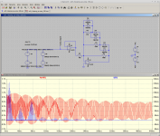
Here's a quick implementation of the above idea. Resistance values have not been optimized - I just threw the circuit together as fast as I could.
R1/R2 set U3's gain to x10 for small signal levels (compare with x11 for the earlier simulations without the diode network).
The diode/resistor network in parallel with R2 roughly halves the voltage gain when the output signal is big enough for D1/D2 to conduct at around +/- 400 mV, halves it again if the signal becomes big enough for D3/D4 to conduct (at roughly +/- 800 mV), and finally clamps it hard if/when D5/D6 conduct (at roughly 1.2V).
The attached image shows no hard clipping at the output (red trace).
The overlaid blue trace shows current flow in D5; evidently the signal does get big enough at some instants to trigger D5/D6.
As mentioned earlier, I don't love the sound of diode clipping - but it may be better than harsh op-amp clipping. And if signal levels and stage gains are set well, D5/D6 may never conduct, or only at the very strongest signal peaks.
-Gnobuddy
Attachments
Decades ago, the concept was used to shape triangle waves into crude approximations of sine waves in audio function generators.
For a sine shaper, a degenerated bipolar differential pair with 2.5 kT/q of bias voltage across the emitter resistors and a triangle of 6.62 kT/q peak works remarkably well: harmonic distortion about 0.2 %. But that's quite off topic.
I still play through the little 4 watt amp that I made for that circus most of the time that I actually use an amp. After the band, dust and clowns went away I ripped the amp open and stuffed a couple of mosfets into it in strategic places to offer far more tonal flexibility. With a fresh non-microphonic input pentode that little amp can offer up some high gain tones that might embarrass a SLO100 without the ear bleeding SPL. I was really into that sound at the time.Thanks for posting that image here. I remember seeing it in one of your posts on the HBAC thread.
By the way, stumbling across the HBAC thread via a Google search - after the brass band had left and most of the dust had settled - was the main reason why I joined diyAudio in the first place. 🙂
One of the more striking things about the guitar waveform you captured is how very spiky it is. That means lots of high overtones, and very little fundamental frequency.
I think that may be the spikiest guitar waveform I've ever seen.
Something to do with the stiff guitar pick, probably, and maybe the pickup position (very near the bridge?).
-Gnobuddy
I need to get that guitar out and figure out how it works. It's not a typical Strat knock off and has some unusual wiring including a tiny switch to run the pickups out of phase. Of course, I have long lost the notes of how the switches were set when I took that picture.
Except for "pointy" waveform peaks!For a sine shaper, a degenerated bipolar differential pair with 2.5 kT/q of bias voltage across the emitter resistors and a triangle of 6.62 kT/q peak works remarkably well
Been there, done that, a few decades ago. Added additional "catching diodes" to help round off the pointy tips. Found out someone had come up with the clever technique of inverting and mixing some of the triangle waveform with the shaped signal, which also does quite a nice job of rounding off those ugly pointy tips.
Eventually found a better sine shaper circuit a few years ago...but, as you say, that's quite off-topic.
More on topic: diyAudio member Bucks Bunny has been using the very same tanh(V/2*Vt) transfer function of a BJT differential pair to provide overdrive and (relatively) soft clipping in his home-grown solid-stage guitar amps. (where Vt = k*T/q, around 25 mV at typical room temperature).
I didn't much care for the sound of those amplifiers in sound clips he posted some years ago. The overdrive sounded harsh, abrupt, and very typically solid-state to my ears, which may have been the cause of some of his grumpiness on this thread.
It's interesting that a long-tailed pair phase splitter in a tube amp has a much more progressive and much less harsh overdrive characteristic, presumably because the voltage gain is so much lower, and the transfer function isn't sharply exponential like a BJT.
(For our purposes, it would have been nice if Vt was a few volts rather than just 25 mV!)
Getting good overdrive out of a SS amplifier is an entirely different topic, though well worth exploring. In this thread, I'm more focussed on understanding and then stopping the low-level harsh "gritty" sound characteristic of so many analogue SS amps.
So far, the simple rules-of-thumb seem to be:
1) Don't use op-amps
2) Don't use significant negative feedback
2) Use a JFET at least at the input
3) Use individual discrete BJT gain stages if FETs won't do.
-Gnobuddy
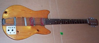
The attached photo was my first electric guitar, a diy project I built some 35 years ago, around a neck and tailpiece from a friend's broken archtop guitar.... some unusual wiring including a tiny switch to run the pickups out of phase.
You can see four little toggle switches on the aluminium control panel.
One of them was a pickup selector. Another one put both pickups in parallel. A third reversed the phase of one pickup.
The forth switch was a rhythm/solo switch, the idea being to drop the signal level a few decibels for strumming chords, then bring it back up to play a guitar solo.
I quite liked the ability to parallel both pickups, then reverse the phase of one. But there were other problems with that guitar (I didn't really know what I was doing when I built it), so I moved on.
I've never had another guitar with a phase-reversal switch. Pity.
-Gnobuddy
Attachments
So maybe a compressor pedal (I have a Boss CE1) in front of a SS amp will better emulate the sound of a Tube Amp? Hmmm...
BTW - A few weeks ago I decided to modify a stereo LM3886 Chip amp to Current drive and it sounded OK on HiFi. But I did the same modification to my LM3886 Guitar amp (which was pretty good to start) made a huge difference. The pedals sounded better, the various Semihollow, solid body, Fender / Gibson / Ibanez guitars all sounded better to me...the amp was driven by a simple preamp I built from the first Roland JC120 (the one with 2SK-117 JFET, not opamp version). The LM3886 Current mod also raised the gain quite a bit - but weird that it didn't for the Current drive Hifi amp...
Also had my wife listen the the modded guitar amp for some crazy noises/harshness (she can still hear up to 18k, while I struggle with 8k), and heard nothing bad, actually said it sounded nice (something she never says)...so I know it sounds "good" if it pleases her.
Next week I take it to Band practice and see if it will unseat my modded Fender Hot Rod Deluxe tube amp. The HRD sounds great, just bloated in upper bass - never could get my head around why...
Was going to sell it but looks like I am keeping it now...
https://www.diyaudio.com/community/threads/roland-jc-120-jazz-chorus-amp-clone.366772/
Also - I have both the guitar pre and Amp PCBs from Elliott Sound Products somewhere - maybe time to build it... That P101 amp is one of my favorite amps! Rod Ranks!
Last edited:
Sorry - I posted the above to ask if the Current Mod I did on the LM3886 could be the reason it appears to be less Harsh / reduced clipping, as it changed the Feedback design...
I'm not sure, never having tried that. (I'm not familiar with the specific mod you did, but I assume you changed the NFB to sense output current rather than output voltage, which would result in a high output impedance rather than a low one. More like a tube amp.)Sorry - I posted the above to ask if the Current Mod I did on the LM3886 could be the reason it appears to be less Harsh / reduced clipping, as it changed the Feedback design...
I built a simple speaker attenuator with resistors for my first tube amp back in 2010 or so. The attenuator dropped speaker volume nicely, but also took away something - the amp didn't sound as good, and seemed to sound more dull. There was "tone suck", as some guitarists put it.
It was quite a few years before I figured out that tube amps have high output impedance, and learned that this allows the speaker's voice coil inductance to cause a rising treble response, basically a gentle treble boost EQ.
My attenuator had a low output impedance, and so it took away that treble boost, leaving the amplifier sounding flatter and duller.
Some years ago I found a website that talked about the effect of amplifier output impedance on speaker frequency response, but I seem to have lost the bookmark. Bummer. 🙁
If the mod you did raised the output impedance of the LM3886 into the region of at least 20 ohms, you probably gained some treble boost as a result. Also some bass boost around the speaker's fundamental resonance. Maybe you heard those changes as less harshness?
-Gnobuddy
Here is what I did...like I said, for my HiFi- OK (not quite done yet), but I really like what it did to my Guitar amp...
https://www.diyaudio.com/community/threads/viral-projects-sort-of.351475/page-4#post-6410089
And the schematic
https://www.diyaudio.com/community/threads/viral-projects-sort-of.351475/page-4#post-6410089
And the schematic
Attachments

Do you find that works for you?So maybe a compressor pedal (I have a Boss CE1) in front of a SS amp will better emulate the sound of a Tube Amp? Hmmm...
I've tried a (guitar) compressor a few times, but was never entirely happy with the result. For me, there were always the same two problems: first, there was always a brief "pop" at the start of each note, while the compressor struggled to adjust to the sudden huge jump in signal amplitude. Second, the compressor took away a lot of "feel" from my playing.
The relatively soft clipping of signal peaks a tube amp is instantaneous and seems to happen only for milliseconds at a time on signal peaks - unlike a compressor, there's no rectifier trying to guess the average signal strength, and no variable gain cell trying to adjust the gain accordingly. When set for clean tones, this doesn't take away any playing dynamics or "feel".
The late Fred Nachbaur's "Spunky" DIY tube guitar amp had a small-signal pentode input stage, and included a compressor option: speaker voltage was rectified, filtered, and fed back to the control grid of the input pentode to dynamically adjust bias point and voltage gain. I would have thought mixing the control signal with the guitar signal like this would have been a bad idea, but apparently it worked for Nachbaur.
I'm attaching his schematic for this part of his amp.
The full Spunky article is here: http://www.dogstar.dantimax.dk/tubestuf/dv8index.htm#index1
-Gnobuddy
Attachments

Thanks! Yes, that will definitely raise the output impedance of the amplifier (a lot!)
The 0.22 ohm resistor senses current flow through the loudspeaker, and Rf1 feeds back that signal, so the feedback is based on output current, rather than output voltage. And that will make the amplifier try to behave like a constant current source (very high impedance) rather than a voltage source (very low impedance).
I have my doubts if this is a good thing for Hi-Fi (frequency response will be massively mucked-about).
But IMO, high output Z is a good thing for a guitar amplifier feeding an actual guitar speaker, and will give you the EQ curve that the speaker is actually supposed to have in a guitar amp.
-Gnobuddy
and will give you the EQ curve that the speaker is actually supposed to have in a guitar amp.
Yup, but Guitar amp preamp circuits already have that EQ curve buried in its circuit and Tone controls?
Donno, but I like it!
I have my doubts if this is a good thing for Hi-Fi (frequency response will be massively mucked-about).
True, but you can equalize that out with a filter. Current drive of dynamic loudspeakers reduces (non-linear) distortion at frequencies far from resonance. With voltage drive, at frequencies where the back-EMF doesn't dominate the impedance, it's essentially the voice coil impedance that converts the drive voltage into a current that drives the loudspeaker - which would be just fine if the voice coil impedance were linear, but in fact it has some substantial non-linearities. What happens around resonance can be complicated, but some have measured worthwhile distortion reductions also around resonance.
Off topic again, but you started this time 😉
Not sure if the waveforms can be compared to the real world data.
There is a 250 k volume control connected to the pickup directly. Is the waveform measured in the scope with this pot in circuit?
Scopes usually have 10 meg input impedance. If the pickup is directly connected to scope, there is almost no loading. The waveforms may be misleading.
Manufacturers like Peavey, use 220 k input resistors which may actually remove some harsh spikes.
Earlier Jazz chorus amps had even lower input impedance. More high end is pronounced.
These amps do not pronounce the harshness.
When the bass response is reduced, all the amps sound very clean.
Rod Elliot somewhere said, there will not be any sound difference unless the input impedance goes below 68 k.
I believe lower impedance might affect the sustain of the sound but improve over the harshness..
Regards.
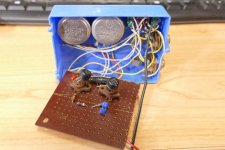
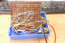
1960's vintage cure for the clipping related nasties, germanium. A typical 60's vintage germanium device will have enough leakage to hide any low level input information. It will not saturate nearly as hard as a silicon device successfully compressing most of the strong signal information. I carefully designed this little device while in high school by dissecting a Vox Tone Bender and tracing it's schematic. I built one with transistor sockets so I could select devices with the best tone. We later discovered that the Vox Tone Bender and the Dallas Arbiter Fuzz Face share the same schematic except for some component values. With both knobs cranked up full you get a decent Jimi sound, but at reasonable settings you can get a good clean tone. There is enough output when dimed to drive the first stage of a Fender 5C1Champ (6SJ7 into 6V6) into complete blocking for over a second. The original 5C1 has grid leak bias with a 4.7 meg resistor.
I made this one somewhere around 1968 or 1969 and still have it. My later versions used relays controlled by a pedal.
I made this one somewhere around 1968 or 1969 and still have it. My later versions used relays controlled by a pedal.
Attachments
- Home
- Live Sound
- Instruments and Amps
- Discussion: Unwanted clipping in solid-state e-guitar preamps