LM317T With a divider current of 3.5mA could work. If you Zener protect it and use some cooling like a SK104 or similar. This would allow the use of a 6AV5GA too.If the LM317L goes into thermal shutdown, and the load is still connected, won't the pass tube then be taking all the load current? Or does the LM317L go completely open circuit once in thermal shutdown, and the tube will then have no plate current through it?
If you use an 82R adjust resistor, you're getting 12mA current through the 1.25V reference. Is that really necessary?
What would be the problem with making the adjust resistor 470R instead, with about 2mA current through the reference?
The problem is that if I drag 12mA through the reference, that's taken away from the 40mA capacity of the power transformer, leaving the maximum load current at only 28mA.
Also, I'm finally seeing why you've been advising to go to a 6AS7.
If the TL783 is necessary, and the grid-cathode voltage of the pass tube must stay at 15V or higher, then a 6AV5-triode will not have enough plate-cathode voltage to accomplish this (its grid bias will have to go more positive than -15V). Since the 6AS7 can operate at lower plate voltages than 6AV5-triode, it leaves a 15V or higher voltage 'window' within which the TL783 can operate.
If I used an LM317T instead (let's say on a decent heatsink to keep it from thermal shutdown), I could then get away with a 6AV5 as the pass tube, as it requires only 3V in>out. But you mentioned situations that could destroy the LM317, which I'm not sure I understand completely. If the LM317T can be kept from going into thermal shutdown, what are other ways it could fail using it in the above circuit?
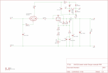
This is what I have now. It looks like it's adjustable from 270V to 355V, staying in regulation and staying just barely within the 40mA current budget with a 35mA load. The TL783 will definitely need a heatsink, as it will dissipate up to 1.7W. The adjust resistor (R1) has 4mA through it as shown.
View attachment 1089845
Ideally you find a slightly beefier transformer, and use the 783 with some output capacitance like 22uF or so. You can use bypassing on the Adj pin to lower noise even further, but you need to add some series resistance so the cap cannot damage the protection diode between adj and out.
Say you could find another transformer that fits the bill.
You could then use the transformer you have with a 150V neon tube to build a floating screen supply for two 6AV5G's and build a bench power supply capable of feeding whatever you need.
Thank you once again for sharing your thoughts on my hare-brained design. I really appreciate it.
One of my goals for this project is take some parts I've collected over the years and put them to good use. I don't want to purchase any more new transformers at the moment.
However, I have a couple bigger transformers lurking in the closet, pulled from old junked power supplies. You've given me great information on how to use one of those to make a higher current-capable 400V or so regulated supply.
Regarding the resistor in series with the ADJ pin bypass cap, what value is used for that? I figure 10 ohms should suffice.
Also, if the capacitance is kept to a low value, for instance 1uF, it could be an electrolytic part with high ESR. The ESR of a typical 1uF 400V electrolytic cap is about 1.5 ohms. The time constant need only be around 100ms, so 1uF in parallel with 110k ohms would be OK, I think.
I was rummaging around in my parts and found a few LM317HV. Does that help?
Is this for a preamp or an amp? If the former my recommendation is rectification > smoothing > CCS > glow tube stack. Zero point zero hum with a source impedance in the 300 ohm range.I was thinking of making a 300V DC supply for tube preamp projects
It's for a preamp, using a 700VCT 40mA transformer, so I'm only going for 35mA max load current.
For a power amp, rectifier > C-(small)R-C > CCS > VR tube stabilization would be fun to try.
For a power amp, rectifier > C-(small)R-C > CCS > VR tube stabilization would be fun to try.
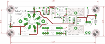
This project needs a PCB made for it methinks so i sat down long enough to draw one. Made it in Inches as well, so no problem using metric to inches conversion.
Attached the gerbers for the 6AV5GA based maida regulator using TL783 or LM317HV.
You can order these boards from JLCPCB.COM with the attached gerbers. Shouldnt cost more than 17USD shipped for 5Pc.
Price comparison for printed circuit boards can be found on PCBSHOPPER.COM
Cooler is a SK129-50 socket is a VT8 from Belton.
Also attached are the board files in EAGLE format so you could edit these if you wish.
Attachments

Very nice.
And if you want one of my boards, I can probably send it as letter mail for about 5$... LMK if you want one.
And if you want one of my boards, I can probably send it as letter mail for about 5$... LMK if you want one.
Active screen and plate regulation were both tried on a pentode SE project. The screen was a regulator on top of a glow tube but it was found that even with that highly dynamic load under clipping conditions the improvement in screen regulation was minimal at best. It's hard to see an operating condition for a preamp that strains a simple VR bulb.I'm only going for 35mA max load current.
The plate regulator was replaced with 0.6H 11 ohm chokes. Residual output hum is 0.5 mv with max 1 volt B+ shift on a 380 Vdc supply, good enough for me to drop the additional active complexity.
You are right in assuming that neon regulation would be sufficient, however there is something to be said for a good Maida regulator once in a while. They are pretty much indestructible if well constructed and offer similarly low output noise levels with the benefit of better DC regulation.
My bias towards minimum parts count and active devices doesn't invalidate the active approach. Would make for an interesting comparison.
v4lve lover,
THANK YOU for creating that circuit and the gerbers! That was really generous of you to do that.
rdf,
I would love to have an old-fashioned CLC after rectification > big triode pass tube > VR tube 'string' PSU. That would be cool just to have for vintage tube street cred alone! As I see it, the downsides are
1) the two 0D3s need to consume at least 10mA for low noise (or am I wrong about that and 5mA would be sufficient?),
2) the B+ voltage will probably end up being a bit lower than +300V, and
3) the B+ would not be adjustable.
The upsides are
1) It will be really pretty with all those tubes and iron things up top, and
2) it will use parts I've collected since the mid-1980s, and
3) it might sound good!
Would I make a +300V PSU like that by using two 0D3s in series, preceded by a choke input supply (LC after the rectifier) of about +330V (an extra 30V to make sure the 0D3s strike at power up)?
Or is it better to use a CLC or CRC to a big triode pass tube and then the VR string?
Hold my Energy drink, I think i designed that PCB with the socket and heatsink on the same side.v4lve lover,
THANK YOU for creating that circuit and the gerbers! That was really generous of you to do that.
The upsides are
1) It will be really pretty with all those tubes and iron things up top, and
You will need more than an extra 30V to get them to light up. Minimum supply voltage is 185V for an 0D3 so 370V will work but 400V will always strike them even as they age.Would I make a +300V PSU like that by using two 0D3s in series, preceded by a choke input supply (LC after the rectifier) of about +330V (an extra 30V to make sure the 0D3s strike at power up)?
Alternative would be 330V and one 0D3 in series with a zener string.

You can put a big resistor across one and only one of them to reduce the required extra voltage.
Hold my Energy drink, I think i designed that PCB with the socket and heatsink on the same side.
Well, I could probably import the gerbers into Sprint Layout and fix any problems. That would be instructive for me to do, anyway.
I think I'd rather have all parts other than the tube socket on the PCB with pads for wires connecting to the octal socket pins. The PCB would then be quite small, allowing placement really close to the octal socket. I have lots of good chassis-mount octal sockets.
I also saw what looks like a few traces going nowhere on the 'board dimensions' png image. The ADJ pin on the TL783 looks like it's not connected(?). Or maybe that image is showing the traces on only one side of the board, and the rest of the connections are on the other side.
I didn't see this model on Bob's website. Can you provide a link, or upload the model itself?I used a Bob Cordell model for the TL783.
View attachment 1089368
Ahem! ... that is not a Shunt voltage regulator.
Active element 6AV5A is in SERIES with load.
LM317 too.
I misremembered where I found that model. Let's say that the model could be suspect. I haven't tested it thoroughly against the real life device.I didn't see this model on Bob's website. Can you provide a link, or upload the model itself?
Code:
* TL783C voltage regulator "macromodel"
* subcircuit
* created using Parts release 5.3 on 04/08/93
* at 15:09
* PARTS is a MicroSim product.
*
*  connections: input
*               | adjustment pin
*               |  |   output
*               |  |   |
.SUBCKT TL783C IN ADJ OUT
*
* POSITIVE ADJUSTABLE VOLTAGE REGULATOR
JADJ IN ADJ ADJ JADJMOD
VREF 4 ADJ 1.27
DBK IN 13 DMOD
*
* ZERO OF RIPPLE REJECTION
CBC 13 15 8e-010
RBC 15 5 1000
QPASS 13 5 OUT QPASSMOD
RB1 7 6 1
RB2 6 5 85.21
* CURRENT LIMITING
DSC 6 11 DMOD
ESC 11 OUT VALUE={1.96-0.01057*V(6,5)*V(13,5)}
*
* FOLDBACK CURRENT
DFB 6 12 DMOD
EFB 12 OUT VALUE={2.326-.03221*V(13,5)+0.0001421*V(13,5)*V(13,5)-0.02*V(13,5)*V(6,5)}
EB 7 OUT 8 OUT 8.069
*
* ZERO OF OUTPUT IMPEDANCE
RP 9 8 100
CPZ 10 OUT 1.989e-006
DPU 10 OUT DMOD
RZ 8 10 0.1
EP 9 OUT 4 OUT 100
RI OUT 4 100MEG
.MODEL QPASSMOD NPN (IS=30F BF=50 VAF=94.64 NF=7.604)
.MODEL JADJMOD NJF (BETA=8.3e-005 VTO=-1)
.MODEL DMOD D (IS=30F N=7.604)
.ENDS
*- Home
- Amplifiers
- Power Supplies
- For tube amp B+: Shunt voltage stabilizer using 6AV5GA, LM317, and two 0D3 VR tubes. Dumb idea?