I was thinking of making a 300V DC supply for tube preamp projects using parts I have taking up space.
I wouldn't mind using a couple of 0D3 VR tubes, since I have a couple and they glow a pretty lilac color.
I also have a couple of 6AV5GT tubes I'll never use.
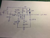
So here is what I've come up with:

In simulation it looks too good to be true. Which means it probably isn't going to work. I have questions...
1. Will the 0D3 tubes strike reliably? If they don't, will that pop the LM317?
2. I figure the output voltage will come up slowly as the 6AV5GT warms up. During that time the pass tube is warming up, will the LM317 get over-voltaged?
3. The value of R4 was chosen to draw 10mA, which I think should be enough to light up the 0D3 VR tubes. Is 10mA too much current for the LM317 reference? I usually see 240 ohms in that position, which means 5mA.
4, I can't visualize what the circuit will do while it's warming up. Do any of you more experienced and knowledgeable folks see something wrong here?
Here's what LTspice thinks the ripple rejection will look like, with the circuit as shown above, with 1V AC ripple riding on the input DC:

Will it work? Or will the LM317 just go 'pop'?
I wouldn't mind using a couple of 0D3 VR tubes, since I have a couple and they glow a pretty lilac color.
I also have a couple of 6AV5GT tubes I'll never use.
So here is what I've come up with:
In simulation it looks too good to be true. Which means it probably isn't going to work. I have questions...
1. Will the 0D3 tubes strike reliably? If they don't, will that pop the LM317?
2. I figure the output voltage will come up slowly as the 6AV5GT warms up. During that time the pass tube is warming up, will the LM317 get over-voltaged?
3. The value of R4 was chosen to draw 10mA, which I think should be enough to light up the 0D3 VR tubes. Is 10mA too much current for the LM317 reference? I usually see 240 ohms in that position, which means 5mA.
4, I can't visualize what the circuit will do while it's warming up. Do any of you more experienced and knowledgeable folks see something wrong here?
Here's what LTspice thinks the ripple rejection will look like, with the circuit as shown above, with 1V AC ripple riding on the input DC:
Will it work? Or will the LM317 just go 'pop'?
Last edited:

Not sure why you need the tube?
1M in parallel with the bottom glow tube will help them start.
As long as the zener protection diode can handle the initial surge, I think the LM317 will be fine. They cost pennies, who cares if you blow one up testing? 🙂
You could probably drop an LM317 into my TL783 circuit if you change the 100V zener for a 30V part?
I'd ditch the idea of regulating the ADJ pin with Neon tubes. As the quick turn on of those gas discharge tubes could very well kill the LM317.
If you are certain you will always have a load connected you could go with TL783 instead of LM317 for slightly better noise rejection. I say this because the TL783 requires 10..15mA output current for stability.
You could use the heater winding of the 6AV5G to provide a +17V source with respect to output without increasing the minimum divider current any further. See pic attached, this is what i did on my LR8+MJE350 combo.
To answer question 2: No the LM317 will try to increase the output voltage if the tube is cold, meaning that the device will decrease the voltage over itself.
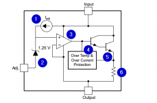
to answer question 3 : no this does not matter, as the Adjust pin is actually a zener bandgap reference 1.25V that is biased up at 10uA. See the attached block diagram of the LM317. In short the output sources the adjust divider current, not the reference.
To answer question 4: Yes a 10mA source will let the tubes strike, but like stated previously this may damage the 317 due to high dV/dT voltages
Edit. Also sorry but the supply drawn is a series type supply, not a shunt. All through shunt regulators with tubes are a feasible proposition, just not very efficient.
Edit, 6AV5 is a decent-ish choice for pass element, but 6C19P 6080 or some other low mu triode made for series duty will have higher efficiency.
If you are certain you will always have a load connected you could go with TL783 instead of LM317 for slightly better noise rejection. I say this because the TL783 requires 10..15mA output current for stability.
You could use the heater winding of the 6AV5G to provide a +17V source with respect to output without increasing the minimum divider current any further. See pic attached, this is what i did on my LR8+MJE350 combo.
To answer question 2: No the LM317 will try to increase the output voltage if the tube is cold, meaning that the device will decrease the voltage over itself.
to answer question 3 : no this does not matter, as the Adjust pin is actually a zener bandgap reference 1.25V that is biased up at 10uA. See the attached block diagram of the LM317. In short the output sources the adjust divider current, not the reference.
To answer question 4: Yes a 10mA source will let the tubes strike, but like stated previously this may damage the 317 due to high dV/dT voltages
Edit. Also sorry but the supply drawn is a series type supply, not a shunt. All through shunt regulators with tubes are a feasible proposition, just not very efficient.
Edit, 6AV5 is a decent-ish choice for pass element, but 6C19P 6080 or some other low mu triode made for series duty will have higher efficiency.
Attachments
Last edited:
Great quality amps of the old days, and still are today, never had the need for a regulated B+.
I personally think it's a waste of time and parts to make something that once was so simple and reliable into a mess of "brilliant ideas".
Or is all this just a modern obsession with things?
I personally think it's a waste of time and parts to make something that once was so simple and reliable into a mess of "brilliant ideas".
Or is all this just a modern obsession with things?
If you enjoy hum on your phono stage, have at it. I regulate because it's cheap, easy, and works better. Also I HATE hum. 😀
Of course nobody needs to regulate B+ on a power amplifier but it makes good sense on high gain signal stages.
The only reason NOT to regulate is the long leed time for TL783 at the moment 🙂
Of course nobody needs to regulate B+ on a power amplifier but it makes good sense on high gain signal stages.
The only reason NOT to regulate is the long leed time for TL783 at the moment 🙂
There is still a place for a nice regulated PSU in my mind, especially for Phono preamps.
Regulating the entire amplifier B+ is feasible.
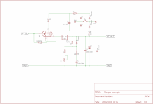
I cranked up the Metallica, and drew you an example of a regulator with TL783. It uses all i have learned over the years in therms of simple improvements.
Regulating the entire amplifier B+ is feasible.
I cranked up the Metallica, and drew you an example of a regulator with TL783. It uses all i have learned over the years in therms of simple improvements.
Attachments
Thanks for the replies, and for your help.
Koda, the only reason to use the tube(s) is that I have some (including 6AV5GT, 6AS7G, 0A2 and 0D3), I need to make a standalone power supply for trying out different preamps (phono and line level), and I'd like to have the nostalgic glow of tubes on display. It's silly, yes, but that's the design goal. It should also be a pretty decent power supply, although it doesn't have to be the be-all-and-end-all.
I could make a classic all-tube PSU, but that's not likely to perform as well as if I cheat and use a regulator IC as the error amplifier.
v4lve lover, thank you for your suggestions and informative advice. Much appreciated! I have some LR8 in stock, so I could simply make the pass tube+LR8 supply you drew, and at least have a nice pass tube on display. Or, the "Rongon example" you drew up looks adjustable, so that might be even more attractive. Could a TL783 be used in place of the LM317 in that circuit? I suspect it would be OK, but as you can tell, I'm not capable of seeing into the (fascinating web of) unintended consequences that comes from placing each of these parts in different places.
wiseoldtech, I recently made a perfectly good RIAA preamp using a 12AX7 and MOSFET source follower per channel, with an all-passive power supply (CRCRC raw B+ with each channel having its own decoupling, although the heater supply is series regulated with LM317). It worked fine. Very, very little hum, which could have been caused by the plate and heater supply transformers being in the same chassis as the audio PCBs (not supply ripple). But yes, I take your point about unnecessary complexity. I do find that a well thought out passive supply can be dead quiet, and 'sounds good' too. This time I just want to use some tubes, mostly for looks. It's silly, I know.
diyAudio member Elvee contributed a good looking PSU design making use of VR tubes under what looks like a simple two-transistor series regulator. Perhaps (for looks) I could use a couple of 0D3s and let MOSFETs do the heavy lifting. Elvee contributed this a few years ago:

Let's say I have a +400V 40mA raw supply, and I want to regulate down to +350V or so. The load will be only 20 to 40 mA.
First, this supply seems a little odd to me.
I tried scaling up the voltages by adding a second 0A2 under U1, with load sharing resistors R9, R10, and a pot for adjusting Vout (B+).

I varied I1 from 2mA to 100mA, and B+ varied only 0.1V. The Zout has to be very low, so I guess it's a good regulator.
The load current is limited only by the dissipation of the pass element M1. It dissipates 5W with 100mA load; 2.8W at 50mA load.
Ripple rejection is not stellar, being -65dB at 120Hz. But that's probably good enough for a 'raw' plate supply with a stage or two of decoupling afterwards.
The impedance curve is a little strange, but maybe it's good enough...

The attraction for me is that I could sit two 0D3 VR tubes on the top deck, perhaps with an old choke, a vintage power transformer and a #47 pilot light, and get a sort of steampunk look going. I don't think I'll go for an output voltage meter, though.
In the end, it appears I have a choice between sitting an octal tube on top, or a couple of VR tubes on top -- but I can't get both unless I do a plain old-fashioned shunt stabilizer or all-tube series regulator from the olden days.
Koda, the only reason to use the tube(s) is that I have some (including 6AV5GT, 6AS7G, 0A2 and 0D3), I need to make a standalone power supply for trying out different preamps (phono and line level), and I'd like to have the nostalgic glow of tubes on display. It's silly, yes, but that's the design goal. It should also be a pretty decent power supply, although it doesn't have to be the be-all-and-end-all.
I could make a classic all-tube PSU, but that's not likely to perform as well as if I cheat and use a regulator IC as the error amplifier.
v4lve lover, thank you for your suggestions and informative advice. Much appreciated! I have some LR8 in stock, so I could simply make the pass tube+LR8 supply you drew, and at least have a nice pass tube on display. Or, the "Rongon example" you drew up looks adjustable, so that might be even more attractive. Could a TL783 be used in place of the LM317 in that circuit? I suspect it would be OK, but as you can tell, I'm not capable of seeing into the (fascinating web of) unintended consequences that comes from placing each of these parts in different places.
wiseoldtech, I recently made a perfectly good RIAA preamp using a 12AX7 and MOSFET source follower per channel, with an all-passive power supply (CRCRC raw B+ with each channel having its own decoupling, although the heater supply is series regulated with LM317). It worked fine. Very, very little hum, which could have been caused by the plate and heater supply transformers being in the same chassis as the audio PCBs (not supply ripple). But yes, I take your point about unnecessary complexity. I do find that a well thought out passive supply can be dead quiet, and 'sounds good' too. This time I just want to use some tubes, mostly for looks. It's silly, I know.
diyAudio member Elvee contributed a good looking PSU design making use of VR tubes under what looks like a simple two-transistor series regulator. Perhaps (for looks) I could use a couple of 0D3s and let MOSFETs do the heavy lifting. Elvee contributed this a few years ago:
Let's say I have a +400V 40mA raw supply, and I want to regulate down to +350V or so. The load will be only 20 to 40 mA.
First, this supply seems a little odd to me.
- M1, the pass element, is dissipating about 3W, while M2 (error amp?) is dissipating only 47mW.
- At such a low dissipation, what is M2 actually doing?
I tried scaling up the voltages by adding a second 0A2 under U1, with load sharing resistors R9, R10, and a pot for adjusting Vout (B+).
I varied I1 from 2mA to 100mA, and B+ varied only 0.1V. The Zout has to be very low, so I guess it's a good regulator.
The load current is limited only by the dissipation of the pass element M1. It dissipates 5W with 100mA load; 2.8W at 50mA load.
Ripple rejection is not stellar, being -65dB at 120Hz. But that's probably good enough for a 'raw' plate supply with a stage or two of decoupling afterwards.
The impedance curve is a little strange, but maybe it's good enough...
The attraction for me is that I could sit two 0D3 VR tubes on the top deck, perhaps with an old choke, a vintage power transformer and a #47 pilot light, and get a sort of steampunk look going. I don't think I'll go for an output voltage meter, though.
In the end, it appears I have a choice between sitting an octal tube on top, or a couple of VR tubes on top -- but I can't get both unless I do a plain old-fashioned shunt stabilizer or all-tube series regulator from the olden days.
OK, it's a deal!
I used a Bob Cordell model for the TL783.
It looks fine. Really fine, actually.
With a 50mA load, 400V in, 350V out, the TL783 dissipates 845mW.
Ripple reduction (120Hz) is -110dB.

However, if you try to drop more volts, say take 430V down to 300V, the TL783 will require a big heatsink. With a 50mA load, dropping 430V down to 300V, it dissipates 4.7W. I guess the thing to do would be to use a lower voltage raw B+ in the first place.
Since you're using a 560 ohm resistor and a 100uF cap before the TL783, at 50mA that's already -29V, so a 360V raw supply gives 331V at the IN pin on the TL783. The TL783 dissipates 1.1W in that configuration, which is fine with a clip on heatsink.
I suppose a rule of thumb could be to keep the Vin/Vout differential down to about 30V, and the load current </=50mA. Then it's all cheap 'n easy -- both of which I like a lot.
I used a Bob Cordell model for the TL783.
It looks fine. Really fine, actually.
With a 50mA load, 400V in, 350V out, the TL783 dissipates 845mW.
Ripple reduction (120Hz) is -110dB.
However, if you try to drop more volts, say take 430V down to 300V, the TL783 will require a big heatsink. With a 50mA load, dropping 430V down to 300V, it dissipates 4.7W. I guess the thing to do would be to use a lower voltage raw B+ in the first place.
Since you're using a 560 ohm resistor and a 100uF cap before the TL783, at 50mA that's already -29V, so a 360V raw supply gives 331V at the IN pin on the TL783. The TL783 dissipates 1.1W in that configuration, which is fine with a clip on heatsink.
I suppose a rule of thumb could be to keep the Vin/Vout differential down to about 30V, and the load current </=50mA. Then it's all cheap 'n easy -- both of which I like a lot.
Last edited:
Awesome 🙂 Thank you for that. One day, I'll figure out SPICE.
That's what I use for my HP/line and phono stages 🙂
How about with the bridge and fed with AC though? I guess it would be the same? 60Hz and 37kHz? I figure the PSRR will be worse at high frequencies?
I'm powering these using 37kHz square wave in one set up, and 60Hz in the other.
That's what I use for my HP/line and phono stages 🙂
How about with the bridge and fed with AC though? I guess it would be the same? 60Hz and 37kHz? I figure the PSRR will be worse at high frequencies?
I'm powering these using 37kHz square wave in one set up, and 60Hz in the other.
400VAC into a bridge of HER208 or UF4007? I guess you're just putting a ripple on DC in these sims? In that case, make AC1 37kHz 🙂
Actually nevermind... The graph goes up to 100MHz so it's easy to see the ripple rejection at 40kHz 🙂 Still about 80db
Actually nevermind... The graph goes up to 100MHz so it's easy to see the ripple rejection at 40kHz 🙂 Still about 80db
Awesome 🙂 Thank you for that. One day, I'll figure out SPICE.
That's what I use for my HP/line and phono stages 🙂
Well, if I was sane, I'd just try that. So simple, and looks very effective. Cheap and easy too. Very lovable.
How about with the bridge and fed with AC though? I guess it would be the same? 60Hz and 37kHz? I figure the PSRR will be worse at high frequencies?
I'm powering these using 37kHz square wave in one set up, and 60Hz in the other.
You're reaching the limits of my SPICE abilities here. I know what I know how to do, but when it comes to figuring out more complex simulations, my superficial knowledge of physics and SPICE commands puts a wall between what I can and can't do.
I figure you're asking about simulating a switching power supply. I could make AC1 60Hz instead of 120Hz, and add AC2 at 37kHz. What amplitudes should I choose for these?
400VAC into a bridge of HER208 or UF4007? I guess you're just putting a ripple on DC in these sims? In that case, make AC1 37kHz 🙂
Actually nevermind... The graph goes up to 100MHz so it's easy to see the ripple rejection at 40kHz 🙂 Still about 80db
At what amplitude is that 37kHz noise?
Actually, it's 400VAC square wave and I get 400VDC from it.
The transformer version is fed by 330VAC sine and I get about 400VDC from that, too.
If I had to guess say it's a volt of square wave noise from the DC-DC boost converters...
The transformer version is fed by 330VAC sine and I get about 400VDC from that, too.
If I had to guess say it's a volt of square wave noise from the DC-DC boost converters...
Another thing to try is LM317 instead, using 1n5363 for protection since you can actually buy one.
TL783 is on back order until next summer!
TL783 is on back order until next summer!
I put both 60Hz and 37kHz at 1VAC (each), as sine waves.
I don't know if this is a valid reading, but I ran a simple transient analysis and then the FFT graph. Here it is:

Oh, and I have a couple of TL783 in my stash. I should just whip one of these up, as a utility PSU. I could even put a little pot in it and make it adjustable.
But I still want a PSU with a couple of 0D3s glowing purple on its top deck. Those octal VR tubes look really nice.

I don't know if this is a valid reading, but I ran a simple transient analysis and then the FFT graph. Here it is:
Oh, and I have a couple of TL783 in my stash. I should just whip one of these up, as a utility PSU. I could even put a little pot in it and make it adjustable.
But I still want a PSU with a couple of 0D3s glowing purple on its top deck. Those octal VR tubes look really nice.
I use an 0D3 for bias regulation in my 6P45S amp.
I like the Soviet SG2S 75 volt tube better for the glow though... I use it in most of my other amps.


I like the Soviet SG2S 75 volt tube better for the glow though... I use it in most of my other amps.
If you enjoy hum on your phono stage, have at it. I regulate because it's cheap, easy, and works better. Also I HATE hum. 😀
Of course nobody needs to regulate B+ on a power amplifier but it makes good sense on high gain signal stages.
The only reason NOT to regulate is the long leed time for TL783 at the moment 🙂
A couple of RC sections in a row can easily filter off hum to negligible levels. I built a valve MM phono amplifier about a decade ago with an unregulated, filtered supply. Transformer stray field was the only noticeable cause of hum; with the transformer placed a metre away, I couldn't hear any hum, not even with shorted or open input and the volume turned up high enough to clearly hear the amplifier's noise.
What cascaded RC filters are not so good at, is suppressing subsonic voltage fluctuations due to mains voltage variations. Whenever I tried to measure small signals with a scope, I saw the trace randomly moving up and down.
Too many RC filters in series can cause oscillation, too.
Just look at the performance of the circuits above and realize they cost less too 🙂
I've used glow tubes to shunt regulate the first stage of phono, too. They pick up noise if not implemented properly though.
Just look at the performance of the circuits above and realize they cost less too 🙂
I've used glow tubes to shunt regulate the first stage of phono, too. They pick up noise if not implemented properly though.
1. Will the 0D3 tubes strike reliably? If they don't, will that pop the LM317?
They will strike some unpredictable time after the voltage across them exceeds their striking voltage. I have no experience with the 0D3, but the 85A2 reference tubes I measured had delays ranging from a few dozen microseconds to many seconds:
An ordinary neon lamp had an average start-up delay of about 21.6 ms in darkness, about 10 us in daylight.
The delay of the NEC 85A2 and of the ordinary neon lamp in daylight were reproducible, the others varied all over the place from one measurement to the next.
As v4lve lover wrote, chances are that the LM317 blows up as soon as the tubes strike. The voltage between the LM317's output and ADJ pin will become much too large when the ADJ pin voltage suddenly drops. Maybe you can solve that with a string of three or four forward-biased diodes between OUT and ADJ.
3. The value of R4 was chosen to draw 10mA, which I think should be enough to light up the 0D3 VR tubes. Is 10mA too much current for the LM317 reference? I usually see 240 ohms in that position, which means 5mA.
10 mA is the LM317's minimum load current, so I never understood why one so often sees 240 ohm between output and ADJ. With 120 ohm, you know for sure nothing weird happens when there are no other loads than the feedback network.
- Home
- Amplifiers
- Power Supplies
- For tube amp B+: Shunt voltage stabilizer using 6AV5GA, LM317, and two 0D3 VR tubes. Dumb idea?