A couple of RC sections in a row can easily filter off hum to negligible levels. I built a valve MM phono amplifier about a decade ago with an unregulated, filtered supply. Transformer stray field was the only noticeable cause of hum; with the transformer placed a metre away, I couldn't hear any hum, not even with shorted or open input and the volume turned up high enough to clearly hear the amplifier's noise.
What cascaded RC filters are not so good at, is suppressing subsonic voltage fluctuations due to mains voltage variations. Whenever I tried to measure small signals with a scope, I saw the trace randomly moving up and down.
Oh yes, my experience matches yours exactly.
I built that 12AX7 phono preamp with too small a decoupling resistor to the input stage 12AX7. While playing a record, I would hear these weird, low rumbles from time to time. It took me a while to realize that they never happened when I was not playing a record. I put the preamp on the 'scope and saw that there was a subsonic boost around 1Hz. I simulated it in LTspice, being careful to make it display down to 0.1Hz, and it predicted it exactly (!). So I re-designed the preamp to have a 43k ohm decoupling resistor to that first stage. LTspice predicted that would cure the problem, and indeed it did.
I don't know what problems would be created by the B+ slowly wandering around by a couple of volts, up and down.
If I turn up the volume to full blast and I hear hum, there is too much hum.
At this gain though, the sound of me rubbing my finger on the headshell is far louder than the hum, but it's still there and I hate it so now I regulate and put the PSU in a separate box in the rack.
At this gain though, the sound of me rubbing my finger on the headshell is far louder than the hum, but it's still there and I hate it so now I regulate and put the PSU in a separate box in the rack.
As v4lve lover wrote, chances are that the LM317 blows up as soon as the tubes strike. The voltage between the LM317's output and ADJ pin will become much too large when the ADJ pin voltage suddenly drops. Maybe you can solve that with a string of three or four forward-biased diodes between OUT and ADJ.
Thank you Marcel, that's great information. I suppose I can see that the 0D3s would not conduct for perhaps a half-second to a second, and when they did, suddenly the voltage to the LM317 would lift up high. I'm giving up on the VR tube idea, unless I build an all-tube PSU, or perhaps a simple shunt stabilizer.
10 mA is the LM317's minimum load current, so I never understood why one so often sees 240 ohm between output and ADJ. With 120 ohm, you know for sure nothing weird happens when there are no other loads than the feedback network.
That's great to know.
The original data sheets for LM317 showed applications with 240 ohms for the top resistor in the voltage divider. I think everybody's assumed that's the way they should be used.
But what about TL783, or an LM317 used in a Maida regulator? If you pull 10mA through its R from ADJ to OUT, the bottom resistor will need to be a very high wattage type. The usual way to use those is to make the ADJ-OUT resistor value about 620 (approx 2mA), so if the bottom resistor drops 300V x 0.02A = 0.6W. and the resistor can be a 2W type.
Last edited:
I don't know what problems would be created by the B+ slowly wandering around by a couple of volts, up and down.
My circuit had a finite PSRR, so I also saw subsonics at the output (not a 1 Hz oscillation or peak, just slow and random voltage variations that I saw with and without an input signal). In my case it only complicated low-level measurements. In principle it could cause intermodulation with the desired signal in the loudspeaker if it reaches the loudspeaker, but I can't say I ever noticed that it did.

If I turn up the volume to full blast and I hear hum, there is too much hum.
At this gain though, the sound of me rubbing my finger on the headshell is far louder than the hum, but it's still there and I hate it so now I regulate and put the PSU in a separate box in the rack.
My current tube phono preamp has its DC plate and heater supplies (rectified and CRC smoothing) in a separate chassis, with the regulator PCBs located in the audio chassis.
The plate supply regulator is a version of Morgan Jones' Statistical Regulator. It's super quiet and it makes the audio circuit sound really good.
All this went to hell when I built an ESP Project-06 to use with my old Hagerman Bugle PSU in a separate box (+/-15V, regulated). Right now that's my favorite phono preamp. OP-AMPS?? ((( 😱 ))) But that is a different story...
I guess the point is that both you and Marcel are right. For a phono preamp to not have any hum, the PSU needs to be in a separate chassis, and located as far away from the audio circuits as is practical.
That's indeed my experience.
Wiseoldtech once claimed that he could make a hum-free phono preamplifier with the mains transformer in the same enclosure as the preamplifier, but I never managed, neither with transistors nor with valves. My valve circuit (with an AC heater supply and unregulated B+ supply) is perfectly hum-free when the transformer is far from the amplifier, but with the transformer in the same enclosure, I can only get one channel hum-free by experimenting with the transformer orientation. The other then still has a very slight hum.
Wiseoldtech once claimed that he could make a hum-free phono preamplifier with the mains transformer in the same enclosure as the preamplifier, but I never managed, neither with transistors nor with valves. My valve circuit (with an AC heater supply and unregulated B+ supply) is perfectly hum-free when the transformer is far from the amplifier, but with the transformer in the same enclosure, I can only get one channel hum-free by experimenting with the transformer orientation. The other then still has a very slight hum.
The real trick is to be able to make a tube phono preamp with AC heaters that doesn't hum. I've seen people claim to be able to do this, but I'm not inclined to try. I'm not that neat at wiring layout or lead dress, and I think this would require immaculate wiring skills,
But back to the subject at hand...
I have this that we know will work. I made it adjustable, but that's only from about 300V to 345V. Regulation is very good. The TL783 will require a decent heatsink, because it dissipates 3W. I think a clip-on heatsink would be marginal. The ripple rejection is helped by R1-C1-R2-C2. I put that there so that the TL783 wouldn't be dissipating 5W, since I don't want to have to use a really big heatsink.

Then I went back to using a tube... Yes, for looks...

That one can be adjusted from 300V to 380V, but its ripple rejection is worse, but still decent, at -70dB. Its regulation is still good.
I fiddled with a DN2540 CCS as a pass element with a VR tube 'string' of 2x 0D3 to get 300V output, but the regulation is far worse than either of the two above. Since I'm likely to experiment with preamp circuits that draw only about 10mA, and also some bigger circuits that draw up to 35mA, a shunt stabilizer using VR tubes is not going to be versatile enough for this. So I guess I have to give up on those for now...
But back to the subject at hand...
I have this that we know will work. I made it adjustable, but that's only from about 300V to 345V. Regulation is very good. The TL783 will require a decent heatsink, because it dissipates 3W. I think a clip-on heatsink would be marginal. The ripple rejection is helped by R1-C1-R2-C2. I put that there so that the TL783 wouldn't be dissipating 5W, since I don't want to have to use a really big heatsink.
Then I went back to using a tube... Yes, for looks...
That one can be adjusted from 300V to 380V, but its ripple rejection is worse, but still decent, at -70dB. Its regulation is still good.
I fiddled with a DN2540 CCS as a pass element with a VR tube 'string' of 2x 0D3 to get 300V output, but the regulation is far worse than either of the two above. Since I'm likely to experiment with preamp circuits that draw only about 10mA, and also some bigger circuits that draw up to 35mA, a shunt stabilizer using VR tubes is not going to be versatile enough for this. So I guess I have to give up on those for now...
Not sure why you need the tube?
1M in parallel with the bottom glow tube will help them start.
As long as the zener protection diode can handle the initial surge, I think the LM317 will be fine. They cost pennies, who cares if you blow one up testing? 🙂
You could probably drop an LM317 into my TL783 circuit if you change the 100V zener for a 30V part?
View attachment 1089380
The tube is for pretty, but it also will be very reliable, no heatsink required. I also need the large voltage drop because I'll be using a 700VCT 40mA power transformer (an old Thordarson I picked up decades ago from Leeds Radio in Brooklyn, NY).
In simulations (if they can be believed -- which they often can be), I'm seeing that TL783 provides better ripple reduction but less good regulation than LM317. Also, TL783 requires 15V in/out differential and 15mA load current to regulate, while LM317 requires only 3V in/out differential and a couple mA of load current.
Using this circuit with TL783 as an example:
The load current I1 in the schematic is shown as 35mA.
- If I decrease that to 5mA, everything shuts down and the simulation says the output voltage drops to 0. The regulator wakes up at 6mA load current, so I expect there's a grey area where the regulator won't turn on until the load starts drawing more than 10mA or so. I suppose the 6AV5GT pass tube will also be warming up, so this should not be a problem in practice—the supply voltage shouldn't jump up to the full >400VDC before the 783 wakes up. Do I have that correctly?
- If I increase the load current to 60mA, the output voltage drops to 297V because the 783's in/out differential voltage drops to 10V.
- The predicted ripple rejection is spectacular, at -130dB at 120Hz. Thanks to L1 and the pass tube, ripple rejection keeps getting better as frequency goes higher, to an unbelievable -200dB at 20kHz, and staying at about that level all the way out to 10MHz. (Yes I know, this is hard to believe.) C2 (1000pF) levels out a bump in the response from 1kHz to 2.4kHz. That bump is minor, so C2 is completely optional.
- A lot of that ripple rejection comes thanks to L1 and C1. L1 is a small Stancor 7H 550R 50mA choke I picked up from Leeds Radio. That honkin' 180uF 550V cap is a radial snap-in type I got from Apex Jr. The 120Hz ripple is down -55dB at the plate of U2 (the 6AV5). That means the TL783 ripple suppression is -75dB.
Now if I replace the TL783 with an LM317...
- The 317 regulates down to 2mA current load (I1). The output voltage with a 2mA load is 310.65VDC.
- With a 35mA load, output voltage is 310.15V. With an 85mA load, there's still 4V across the 317, and the output voltage is 309.6V. So the regulation is quite good.
- The predicted ripple rejection is 30dB worse than with the TL783, but it's still -100dB at 120Hz. That's good enough, for sure. (This means the LM317 is providing -45dB of ripple suppression.)
--
If these simulations are accurate, this should be a very good 300V regulator. It should be reliable using a TL783. I know the IC likely will not survive a dead short, but the pass tube should. Replacing the IC is an easier repair than replacing both the IC and a MOSFET in a heatsink.
I can't find anything that will go 'pop', but I'm not very good at seeing the underlying complexities of ICs and turn-on characteristics. Does the above look like it will work?
Last edited:
I try for a 30V differential across the TL783.
Uh oh... I can only get >/=15V across the TL783 if I limit the load current to 30mA or less.
In your experience, what happens if the in/out differential is <20V?
Try swapping out the pass tube for something like a 6080/6AS7GUh oh... I can only get >/=15V across the TL783 if I limit the load current to 30mA or less.
With your current setup, the pass tube is limited to -15V between cathode and G1 meaning you either have to run the Zener plus resistor between input/output, increasing the minimum load current. Or run the heaters as a doubler with respect to output like i did in my example.
Or short out the pass tube...
My experience tried to keep the Pd of the TL783 somewhere around 3W to 4W... In my example above with 560R as R1, making it lower R shifts that voltage to the regulator.
Also, even if the standing current is 50mA on R2, it will dissipate the entire B+ while it charges the cap. I've seen a whist of smoke come from R2 during start up when using a 1W part.
The triode'd pass tube adds gain to the circuit, so there is something to be said for using it, besides that it dissipates presumably outside of the enclosure.
The shorted out TL783 with a 100V zener makes me scream internally, as the mains needs to be within spec or the 100V zener will load-dump into the output bypassing the regulator completely. The tube regulator does not have this issue, and will operate from a wider input supply.
Zeners have quite a bit of capacitance, that part will shunt any high frequency noise straight from input to output. Even more than the N-Mos inside the TL783 i think.
The minimum load current for the LM317 is typ 3.5mA to maintain stability, but max is 12mA according to this datasheet: https://www.mouser.com/datasheet/2/308/fairchild semiconductor_lm317ahv-1191591.pdf
This negates any advantages the 317 may have had over the 783. As the spread maximum of the 317AHVT is close to the mean minimum load current of the TL783.
I actually have a TL783 based maida regulator in my bench PSU and its rock solid since i've added a 12mA CCS to the output. with 3.5mA divider current and 12mA CCS current its adjustable between 1.25-350V
If you want to use it as a experimenting supply, one can use a second 6.3VAC winding, double it, and use a BJT+Nmos current source referenced to ground.
Last edited:
Stupid question maybe, but if you set your PSU to 1.25V, doesn't that mean your dumping the rest into the pass device as heat? Or is that just in a shunt regulator?
Can you use an LM2596 and make an adjustable regulator that switches?
Can you use an LM2596 and make an adjustable regulator that switches?
it depends, most vacuum tube loads don't pull that much current at 1.25V.
But you are correct in assuming that that 15mA fixed load will generate 0.015*450V= approx 6.8W? in the two 6P6S-E pass tubes and TL783 combined.
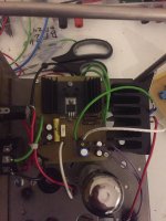
Attached the schematics and a picture of the board, its not pretty but it works.
But you are correct in assuming that that 15mA fixed load will generate 0.015*450V= approx 6.8W? in the two 6P6S-E pass tubes and TL783 combined.
Attached the schematics and a picture of the board, its not pretty but it works.
Attachments

Yes I can, and I have approx 20 LM2596s waiting for an application.Can you use an LM2596 and make an adjustable regulator that switches?
Ive used a LT1076 on a prototype to pre-regulate the input of a LT1085. I used a PNP with a resistive divider to modulate the FB pin of the LT1076 to provide 2V higher input voltage than the output voltage.
Works a charm, but you really need to add SMD 1206 beads to stop the FM from creeping through the 1085 to the output.
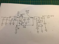
@koda, added an example for you, had to draw up the circuit from memory.
Attachments
Last edited:
With your current setup, the pass tube is limited to -15V between cathode and G1 meaning you either have to run the Zener plus resistor between input/output, increasing the minimum load current. Or run the heaters as a doubler with respect to output like i did in my example.
I'm afraid you've left me in the dust with all that stuff about LM2596 and 1206 beads. The photo of your power supply is downright scary. Those are some serious heatsinks. My motivations for using a pass tube are 1) I already have plenty of tubes and 6.3VAC heater windings, and 2) tubes don't require me to buy heatsinks.
I'm not sure I understand the voltage doubler idea. It looks like it makes the grid (G1) of the pass tube about 12VDC more positive than the output voltage (HT.OUT). Since the output voltage needs to be 15V lower than the TL783 IN pin, and the TL783 IN is at the same potential as the pass tube cathode, I don't see how raising the voltage at the pass tube G1 by +12V will help.
The minimum load current for the LM317 is typ 3.5mA to maintain stability, but max is 12mA according to this datasheet: https://www.mouser.com/datasheet/2/308/fairchild semiconductor_lm317ahv-1191591.pdf
That data sheet is for the LM317HV, the 'high voltage' version that can take up to 50V in>out. The National Semiconductor data sheet for the standard LM317 (35V max in>out) says the minimum load current is 3mA typical, 5mA max. The LM317L (100mA max load current) has the added advantage that its minimum input current requirement is 2.5mA at most, 1.5mA typical.
The power supply I'm discussing here is meant to power smallish tube preamps I'd like to try out, ranging from an RIAA preamp using a couple of 12AX7s with MOSFET source followers presenting a 15mA load current to the PSU, to a stereo pair of 6SN7 common cathode stages (16mA) feeding a pair of MOSFET 'source-o-dyne' phase splitters (16mA) which will present a 32mA load to the PSU. So, I'm aiming for a simple regulator that can provide 300V to 350V DC plate supply at 15mA to 35mA load current. Only modest requirements.
Try swapping out the pass tube for something like a 6080/6AS7G
I have a few old 6AS7G to use. They're the 'coke bottle' shape, so they would look nice. However, the 6.3VCT winding on the power transformer I want to use is not capable of delivering the 2.5A of heater power required by the 6AS7. The 6.3V winding is rated for only 2A. I do have an ugly open-frame transformer rated 6.3V at 3A. Perhaps I could use that for the 6AS7 heater, and use the plate transformer's 6.3VCT 2A and 5VAC 2A windings in series to make an 11.3VAC supply to rectify with a diode bridge and get a smoothed and regulated +12VDC 2A supply. But it would take less work to use the plate transformer's 6.3VCT 2A winding to heat a 6AV5GT (1.2A heater current).
I think this is looking like a possibility...
The LM317L is in a TO-92 package, limited to 100mA output. The idea is to have it go into auto-shutdown if too much current is drawn.
Within the load current limitation of </=35mA at 290V output, the LM317L should dissipate no more than 605mW. Dissipation goes down to 520mW at 300V out with 35mA load current.
If C2 makes it more likely to burn out the VR1 carbon track and/or pop the LM317L, then I could leave it out and accept the ripple suppression of 'only' -80dB at 120Hz.
If D3 (33V zener) makes the output noisier, I could leave that out too.
The LM317L In/Out differential is 3V at its lowest (V+REG = 355V and load current = 35mA). That's enough for an LM317. Or I could put in an LT1085 (I have some) and rest easy.
I think I've thought out all the limitations and compensated for them — except if the LM317 is going to blow up at power on in this type of circuit. But I think it will be OK, since it floats inside the grid-cathode voltage window of the pass tube, and at the voltages and currents we're talking about here, that will never be more than about 30V — or at least that's how LTspice sees it with V+REG = 298.5V and (negligible) load current = 0.1uA.
Thoughts?
Last edited:
ST specifies a minimum load current of 10 mA max. for the LM317, 5 mA max. for the industrial version LM217, and in either case, the accuracy is guaranteed from 10 mA onwards, see https://nl.mouser.com/datasheet/2/389/lm217-1849593.pdf I never knew there was a difference in minimum load current between the commercial and industrial versions.
I'm not sure I understand the voltage doubler idea. It looks like it makes the grid (G1) of the pass tube about 12VDC more positive than the output voltage (HT.OUT). Since the output voltage needs to be 15V lower than the TL783 IN pin, and the TL783 IN is at the same potential as the pass tube cathode, I don't see how raising the voltage at the pass tube G1 by +12V will help.
I think I've thought out all the limitations and compensated for them — except if the LM317 is going to blow up at power on in this type of circuit. But I think it will be OK, since it floats inside the grid-cathode voltage window of the pass tube, and at the voltages and currents we're talking about here, that will never be more than about 30V — or at least that's how LTspice sees it with V+REG = 298.5V and (negligible) load current = 0.1uA.
Thoughts?
That voltage doubler is actually quite smart, as it allows the grid of the 6AV5 to go slightly positive with respects to the input of the LM317. It does however increase the voltage and dissipation over the TL783/LM317.
My power supply uses a TL783 with ~3mA adjust current, and ~12mA CCS on the output so it can remain stable at no output load.
LM317 in TO-92 is no bueno, as the package limitation is 500mW or so. There are operating points where this may cause the chip to go into thermal shutdown. Also if the chip goes into current limit it will increase the voltage over the chip as it normally does. At 450V Vin and a triode 6AV5 it will entail going over the input-output differential of the LM317L. This can happen if you hook up output capacitance, so that zener needs to stay unless you use a TL783.
Better to use a TL783 as this actually has the voltage rating to survive such a thing, as the tube will limit the current during start up before the 900mA limit or so of the TL783 is reached.
For your application, one can take a TL783 with 82R adjust resistor, and just dissipate 4.5W in a series of high power resistors for a fixed output voltage of 300V.
LR8 plus PNP is also an option, but noise rejection figures are at least 20 dB less than TL783.
Edit Package to ambient on the LP package LM317 is 145C/W so if you account for 40C ambient and 500mW dissipation you can get into thermal shutdown or SOA limitations of the internal transistor, meaning the transistor is more likely to act as a Zener diode without reaching 30V input-output.
Last edited:
Thanks for your thoughts on this. Much appreciated. I'm beginning to see what's going on a little more clearly.
If the LM317L goes into thermal shutdown, and the load is still connected, won't the pass tube then be taking all the load current? Or does the LM317L go completely open circuit once in thermal shutdown, and the tube will then have no plate current through it?
What is the situation where I might hook up output capacitance? Do you mean if there is a large capacitor from V+REG to ground, say at the input of the load?
Duly noted.
If you use an 82R adjust resistor, you're getting 12mA current through the 1.25V reference. Is that really necessary?
What would be the problem with making the adjust resistor 470R instead, with about 2mA current through the reference?
The problem is that if I drag 12mA through the reference, that's taken away from the 40mA capacity of the power transformer, leaving the maximum load current at only 28mA.
Also, I'm finally seeing why you've been advising to go to a 6AS7.
If the TL783 is necessary, and the grid-cathode voltage of the pass tube must stay at 15V or higher, then a 6AV5-triode will not have enough plate-cathode voltage to accomplish this (its grid bias will have to go more positive than -15V). Since the 6AS7 can operate at lower plate voltages than 6AV5-triode, it leaves a 15V or higher voltage 'window' within which the TL783 can operate.
If I used an LM317T instead (let's say on a decent heatsink to keep it from thermal shutdown), I could then get away with a 6AV5 as the pass tube, as it requires only 3V in>out. But you mentioned situations that could destroy the LM317, which I'm not sure I understand completely. If the LM317T can be kept from going into thermal shutdown, what are other ways it could fail using it in the above circuit?
This is what I have now. It looks like it's adjustable from 270V to 355V, staying in regulation and staying just barely within the 40mA current budget with a 35mA load. The TL783 will definitely need a heatsink, as it will dissipate up to 1.7W. The adjust resistor (R1) has 4mA through it as shown.

LM317 in TO-92 is no bueno, as the package limitation is 500mW or so. There are operating points where this may cause the chip to go into thermal shutdown. Also if the chip goes into current limit it will increase the voltage over the chip as it normally does. At 450V Vin and a triode 6AV5 it will entail going over the input-output differential of the LM317L. This can happen if you hook up output capacitance, so that zener needs to stay unless you use a TL783.
If the LM317L goes into thermal shutdown, and the load is still connected, won't the pass tube then be taking all the load current? Or does the LM317L go completely open circuit once in thermal shutdown, and the tube will then have no plate current through it?
What is the situation where I might hook up output capacitance? Do you mean if there is a large capacitor from V+REG to ground, say at the input of the load?
Better to use a TL783 as this actually has the voltage rating to survive such a thing, as the tube will limit the current during start up before the 900mA limit or so of the TL783 is reached.
Duly noted.
If you use an 82R adjust resistor, you're getting 12mA current through the 1.25V reference. Is that really necessary?
What would be the problem with making the adjust resistor 470R instead, with about 2mA current through the reference?
The problem is that if I drag 12mA through the reference, that's taken away from the 40mA capacity of the power transformer, leaving the maximum load current at only 28mA.
Also, I'm finally seeing why you've been advising to go to a 6AS7.
If the TL783 is necessary, and the grid-cathode voltage of the pass tube must stay at 15V or higher, then a 6AV5-triode will not have enough plate-cathode voltage to accomplish this (its grid bias will have to go more positive than -15V). Since the 6AS7 can operate at lower plate voltages than 6AV5-triode, it leaves a 15V or higher voltage 'window' within which the TL783 can operate.
If I used an LM317T instead (let's say on a decent heatsink to keep it from thermal shutdown), I could then get away with a 6AV5 as the pass tube, as it requires only 3V in>out. But you mentioned situations that could destroy the LM317, which I'm not sure I understand completely. If the LM317T can be kept from going into thermal shutdown, what are other ways it could fail using it in the above circuit?
This is what I have now. It looks like it's adjustable from 270V to 355V, staying in regulation and staying just barely within the 40mA current budget with a 35mA load. The TL783 will definitely need a heatsink, as it will dissipate up to 1.7W. The adjust resistor (R1) has 4mA through it as shown.
Last edited:
- Home
- Amplifiers
- Power Supplies
- For tube amp B+: Shunt voltage stabilizer using 6AV5GA, LM317, and two 0D3 VR tubes. Dumb idea?