Hello everyone,
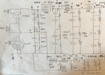
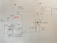
I have a 211 amplifier (circuit included below) and I have determined the existing power supply configuration and I am considering changing the Power supply caps from electrolytic to Film Oil (ASC X386S) based on popular opinion. The electrolytic caps are 20 years old, and having some exchange with another DIYer he suggested that a single CLC sounds better than multiple in a row CLCLCLC like I currently have. Your thoughts welcome on the topic of PS design, I have attempted as a layman to use the PDUD2 software to predict the ripple and response. I am sort of unclear on the criterion for a good PS based upon the article by Rob here which seems to suggest the slope on start up is indicative to the behaviour in use?
What apart from the obvious reduce ripple and hit the right voltage are the criterion for using PSUD2 to compare the designs?
Hopefully not a too stupid question!
Thanks!
Attachments
He's wrong. Every stage needs its own decoupling. And there is no reason to change a working design.he suggested that a single CLC sounds better than multiple in a row CLCLCLC

Thanks for the reply, do you still think of each inductor as a stage if they are joined in series?He's wrong. Every stage needs its own decoupling. And there is no reason to change a working design.
Have you used the PSUD2 software to design a power supply, and if so what do you look at beyond the voltage and ripple outcome?
1. No. Inductors in series simply add. They don't comprise separate filters. Just like capacitors in parallel.
2. You don't need PSUD2 to know that a sixth-order filter attenuates three times as quickly as a second-order filter.
2. You don't need PSUD2 to know that a sixth-order filter attenuates three times as quickly as a second-order filter.
agreed so we are comparing a single CL(with higher total inductance)C to a series of CLCLCLC - a similar comparison was shared in the article of the original post, concluding that the CLC was superior to multiple stages.1. No. Inductors in series simply add. They don't comprise separate filters. Just like capacitors in parallel.
This implies an answer from my question that the only thing that matters is ripple reduction, which is as shown and obvious to the more expeirenced superior in the CLCLCLC, so leave alone.2. You don't need PSUD2 to know that a sixth-order filter attenuates three times as quickly as a second-order filter.
BUT the article implies it's not so simple, hence the question on interpreting the plots beyond lower ripple = better.
It is impossible to discuss unsubstantiated claims like those in your cited article.
Last edited:
Hey - thanks again for the reply.It is impossible to discuss unsubstantiated claims like those in your cited article.
The knowledge gap I have is the design goals and use of simulation to achieve and guide these for a power supply. I am not concerned about the efficacy of the articles claims of superior (and my friend's) sound quality in a single CLC design, although I have no particular reason to doubt their opinion.
However the simulated results suggest, using PSUD2, that it's not as simple as ripple and supply voltage alone, which I am sure is the case. What would be great to understand is what could the simulation software show that a change of design creates, and what as a design intent makes a better outcome in this context.
It's difficult to know where to start. Almost all of your citation is unsubstantianted, and much of it is self-contradictory. For example, inductor ESR bad, transformer ESR good. As for unsubstantiated, take the claim that a PSU needs an optimal Q, or the claim that the performance on initial charging has anything to do with the steady-state performance. Or the claim that it sounds better: define 'better'. Some of it is wrong, for example the apparent claim that only increasing transformer ESR can increase the conduction angle, or that only series R causes channel separation. Or the implicit claim that a PSU should be treated as a filter only.
The most relevant of all this nonsense is the implicit claim that the startup as modeled by PSUD looks anything like the real startup with real valves, which takes not 1000mS but 40S.
The real question you need to answer, rather than trying to validate or refute arbitrary Internet ramblings, is what problem are you trying to solve? At 1000V you are going to get a LOT of ripple, and you need to tame it. First. And the PSU you are starting with looks like it already does a good job of that: unlike your proposed mod, which won't.
interestingly this was why I wanted some additional input as I also could not understand how the start up from 0V to supply voltage was indicative of the performance in use, however I recognise that power supplies do fundamentally affect the sound quality, and this article peaked my interestIt's difficult to know where to start. Almost all of your citation is unsubstantiated, and much of it is self-contradictory. For example, inductor ESR bad, transformer ESR good. As for unsubstantiated, take the claim that a PSU needs an optimal Q, or the claim that the performance on initial charging has anything to do with the steady-state performance. Or the claim that it sounds better: define 'better'. Some of it is wrong, for example the apparent claim that only increasing transformer ESR can increase the conduction angle, or that only series R causes channel separation. Or the implicit claim that a PSU should be treated as a filter only.
The most relevant of all this nonsense is the implicit claim that the startup as modelled by PSUD looks anything like the real startup with real valves, which takes not 1000mS but 40S.
What I am doing is changing the old electrolytic capacitors as they have been in service for over 20 years and I have replaced similarly old power supply capacitors in other amplifiers and heard obvious improvements in sound quality in a commercial amplifier i have not medalled with the values chosen. In some cases I have also seen evidence of electrolyte leakage, requiring attention.The real question you need to answer, rather than trying to validate or refute arbitrary Internet ramblings, is what problem are you trying to solve? At 1000V you are going to get a LOT of ripple, and you need to tame it. First. And the PSU you are starting with looks like it already does a good job of that: unlike your proposed mod, which won't.
1. Why was the original design created as it is currently configured?
Because it was a modification of an unfinished DIY design of a different circuit and used the same PS components in a new layout.
2. Is it optimal?
I have no idea > hence the enquiry. This is a one-off amplifier, and was not developed through multiple versions to create a finished/preferred solution.
3. What capacitors should I consider, as the original supplied units are no longer available?
Many people, whom I respect their opinion on sound quality like the sound of the ASC mineral oil caps, and a large number of people (myself included) prefer not to use electrolytic wherever possible as their sound signature can be bettered IMO to my ears and experience. Hence I started to look here. Clearly if you are interested in SET amplifiers and have invested in such an amplifier the SQ is the fundamental reason why.
Thanks for all the help and opinion,
Hello everyone,
I have a 211 amplifier (circuit included below) and I have determined the existing power supply configuration and I am considering changing the Power supply caps from electrolytic to Film Oil (ASC X386S) based on popular opinion. The electrolytic caps are 20 years old, and having some exchange with another DIYer he suggested that a single CLC sounds better than multiple in a row CLCLCLC like I currently have. Your thoughts welcome on the topic of PS design, I have attempted as a layman to use the PDUD2 software to predict the ripple and response. I am sort of unclear on the criterion for a good PS based upon the article by Rob here which seems to suggest the slope on start up is indicative to the behaviour in use?
What apart from the obvious reduce ripple and hit the right voltage are the criterion for using PSUD2 to compare the designs?
Hopefully not a too stupid question!
Thanks!
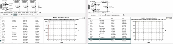
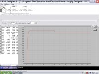
PSUD2 like you have it doesn't tell much. Can you run it again with the settings like this for the 3 choke version: "for 20 ms after a reporting delay of 30 seconds". Then check the box for V at R2. This will display the ripple out to 6 decimal places and make it easier to compare, right now its just whole number volts. With 3 big chokes like that you should be 25uV or less even of ripple!
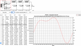
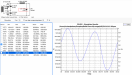
Here are plots of the two configurations and the ripple on the existing design is incredibly small, and the ripple on the new alternative design is NOT that small.
Obviously IF the only criterion is low ripple then the existing design layout is better, BUT if the reality is the new design is more responsive and has less 'ringing' if that is what is inferred and a better Sound quality and has acceptable hum (through the transformer into the speakers this is gong to be reduced somewhat further) then this is better.
It seems like everyone uses PSUD2 to predict the ripple and voltage only and not use it to predict other areas of the circuit response that contribute to the over all performance?
I can put together a design topology that minimises the ripple and sustains the target voltage, with alternative replacement capacitors, and what I am looking for is any knowledge and guidance on what criterion my designs should be judged by.
Ejp obviously thinks the article is utter nonsense, I am more open minded to understand if there is any merit in this article and to understand what else should be considered.
Attachments
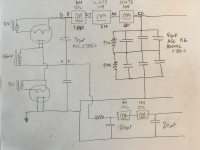
In the single choke design you won't find a 30H choke with enough current capacity for a 211, it would be as big as your chassis! At 200ma that 30H choke is doing nothing but getting hot. If you must do anything. I'd keep the old PS but replace the electros with high voltage DC link film caps because its a good idea to replace electros anyway. This way the signal doesnt pass through the last cap electro but passes through a cap film instead. Also I'd step up the capacitance instead of 55uf all the way, go 40, 80, 100 left to right all DC link.
Thanks for the advice, re the chokes: the current Chokes will go in series to create 30H = 10+10+10, so they will have the current capacity, as they already take the 211 current.In the single choke design you won't find a 30H choke with enough current capacity for a 211, it would be as big as your chassis! At 200ma that 30H choke is doing nothing but getting hot. If you must do anything. I'd keep the old PS but replace the electros with high voltage DC link film caps because its a good idea to replace electros anyway. This way the signal doesnt pass through the last cap electro but passes through a cap film instead. Also I'd step up the capacitance instead of 55uf all the way, go 40, 80, 100 left to right all DC link.
What is a sensible objective for residual ripple mV on the simulation, I have had it explained to me that the actual hum transmitted to the speakers will be less, through the turns ratio acting as a potential divider.
Last edited:
Thanks for the advice, re the chokes: the current Chokes will go in series to create 30H = 10+10+10, so they will have the current capacity, as they already take the 211 current.
What is a sensible objective for residual ripple mV on the simulation, I have had it explained to me that the actual hum transmitted to the speakers will be less, through the turns ratio acting as a potential divider.
I'm a Newby so can't answer your question, but I have recently built an LCLCLC power supply capable of 300ma variable from 0 to 1,000 volts with 300ma chokes and DC link capacitors for use as my unregulated bench supply for breadboarding. I hook it to a variac and step up transformer to get any unregulated variable voltage I need on the bench. It puts out no more than 10uv of ripple at 200ma and immeasurable ripple at 20ma. and I'm very happy with it over my commercial regulated bench supplies by Heathkit and Eico, which keep blowing out parts on me. IOW The choke input is all the regulation I need on the bench. I've never heard of the theory of using a single huge choke and cap as sounding better. I think LCLCLC removes your ripple headaches permanently, and that last DC link capacitor is a sonic improvement over the music having to pass through an electrolytic last cap.
Last edited:
The plot thickens.... the guy (he is pretty experienced and has built many amps, he also sells components so has access to a lot of choice on his builds, made the point that CLC is better than CLCLCLC to his hearing (he said multiple chokes filters cab interact and cause some high speed resonances / ringing). He also said it's the FIRST cap that makes the biggest difference to SQ, and if you have to use electrolytic use them last and put the oil/film first!I'm a Newby so can't answer your question, but I have recently built an LCLCLC power supply capable of 300ma variable from 0 to 1,000 volts with 300ma chokes and DC link capacitors for use as my unregulated bench supply for breadboarding. I hook it to a variac and step up transformer to get any unregulated variable voltage I need on the bench. It puts out no more than 10uv of ripple at 200ma and immeasurable ripple at 20ma. and I'm very happy with it over my commercial regulated bench supplies by Heathkit and Eico, which keep blowing out parts on me. IOW The choke input is all the regulation I need on the bench. I've never heard of the theory of using a single huge choke and cap as sounding better. I think LCLCLC removes your ripple headaches permanently, and that last DC link capacitor is a sonic improvement over the music having to pass through an electrolytic last cap.
Some points, in no necessary order and given in love and hope, not because I am an expert.The plot thickens.... the guy (he is pretty experienced and has built many amps, he also sells components so has access to a lot of choice on his builds, made the point that CLC is better than CLCLCLC to his hearing (he said multiple chokes filters cab interact and cause some high speed resonances / ringing). He also said it's the FIRST cap that makes the biggest difference to SQ, and if you have to use electrolytic use them last and put the oil/film first!
1. Hearing is not a great test instrument.
2. A power supply doesn't (or shouldn't) have a sound. Its job is to provide a stable clean energy source to the rest of the system.
3. The operation of a power supply is ruled by physics, not voodoo.
A good primer on power supplies including decoupling and various mildly but not threateningly technical details is avaialable from merlinb at https://www.valvewizard.co.uk/. Its not as technically thorough as the RD4, but it reads a lot better and doesn't require a degree in electrical engineering.
agreed but it does have to be the final judge. I am my sure my old solid state power amp measures significntly better in all areas, but it does not sound better.Some points, in no necessary order and given in love and hope, not because I am an expert.
1. Hearing is not a great test instrument.
It is often quoted that the power supply is one of the most important elements within any design, and it's relatively common to buy better power supplies within a range of products purely to improve the sound quality (Naim audio being a classic example) so in effect you always hear it.2. A power supply doesn't (or shouldn't) have a sound. Its job is to provide a stable clean energy source to the rest of the system.
agreed, what I am after is some knowledge of the science to explain what may be voodoo or personal subjective opinion.3. The operation of a power supply is ruled by physics, not voodoo.
I was helpfully advised to look at PSUD2 as a tool to apply physics to model any system changes, and what I am after is some guidance on what the simulations should be designed to achieve, beyond the correct voltage and low ripple.
Thanks for the link, I will have a read up on this 🙂A good primer on power supplies including decoupling and various mildly but not threateningly technical details is avaialable from merlinb at https://www.valvewizard.co.uk/. Its not as technically thorough as the RD4, but it reads a lot better and doesn't require a degree in electrical engineering.
It still surprises me that people still think that everything that can be heard can be measured with a clear correlationSome points, in no necessary order and given in love and hope, not because I am an expert.
1. Hearing is not a great test instrument.
2. A power supply doesn't (or shouldn't) have a sound. Its job is to provide a stable clean energy source to the rest of the system.
3. The operation of a power supply is ruled by physics, not voodoo.
A good primer on power supplies including decoupling and various mildly but not threateningly technical details is avaialable from merlinb at https://www.valvewizard.co.uk/. Its not as technically thorough as the RD4, but it reads a lot better and doesn't require a degree in electrical engineering.
It would be easy just get a flat line with DSP and live happily ever after
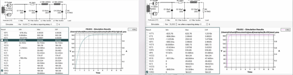
A psu primary function is ripple filtering but this is not the whole story. Its output impedance across audio band is also important. Too high and B+ will sag at transients, too low and it will ring. There is a way to look for this in PSUD2 and this is the start up slope if regarded as a load variation. Or use a stepped load.
Attachments
Similarly, it still surprises me that people think stuff can be heard that cannot be measured. I differentiate between "able to be measured" and "knowing what and how to measure".It still surprises me that people still think that everything that can be heard can be measured with a clear correlation
It would be easy just get a flat line with DSP and live happily ever after
However, this is not a subjective/objective argument. In a power supply it is very easy to measure key parameters that influence the sound output. Voltage sag and ripple (including any harmonics) are trivial to measure and the audible fingerprint of them is clear.
- Home
- Amplifiers
- Tubes / Valves
- Reconfiguring an existing Power Supply using PSUD2 - could use some second opinions :-)