I'm not sure that I can comment on your in room test results, I will say however that you really need to run the amp in for a while after the mod, those caps need some time and it'll sound bright for sure at the beginning in a way that may make sibilance more prominent. Let it run in for a for some solid time.
rereading this and what I find interesting is that my experience has the order from bright to warm completely opposite to yours, I find bridged parallel the warmest and bridged balanced the brightest...I want to contribute my findings.
I have completed the ACA v1.8 build with the mods as suggested by TungstenAudio and Zamjazz27.
The build changes from stock:
===========================
C1: 4700 uF, 35V; Nichicon KG series "Gold Tune" (output capacitor)
C2: 1000 uF, 16V; Nichicon RNL series Aluminum Organic Polymer
C4: 100 uF, 35V; Nichicon RL8 series Aluminum Organic Polymer (power rail bypass)
R3: 0.56Ω 3W 2% metal oxide or film resistors (R3 &R4 changes request reset to bias voltage to 12.4v)
R4: 0.56Ω 3W 2% metal oxide or film resistors (R3 &R4 changes request reset to bias voltage to 12.4v)
R11: 20 kOhm, 1/4W, 1% metal film (Input Resistor), stock was 10k
R12: 90.9 kOhm, 1/4W, 1% metal film (Feedback Resistor), stock was 39.2k
Q1/Q2: FQH44N10 - at 24v just a drop in replacement
68.1 kOhm Bridging Resistor: 1/4W, 1% metal film. bridge Resistor (R16) to replace the stock 39k (If one has a modified ACA with 20k for R11 and 90.9k for R12, then the bridging resistor needs to be 68k in order to balance the levels of the two boards. the 68.1k resistor is only for bridge mono)
C101: 10 pF, 500V, 5% Silver Mica; added in parallel w/ R12 - First choice would be film (polypropylene or polystyrene)
, second choice silver mica. Avoid ceramic, even NPO/C0G could have adverse sonics.
===========================
After the completed build I performed various listening tests cycling through the different connection options (stereo/Mono XLR Bridged/Mono RCA Bridged/Mono RCA Parallel).
What I noticed could be described as a sibilance. I spent several hours cycling through the connection options and always with some options it was an unmistakable sibilance (esses). So I broke out Room EQ Wizard and took measurements of each connection option. Each measurement consisted of exactly the same speakers, exact same location for speakers and mic, exact same cables/wire except for RCA vs. XLR of course, and I found the following:
These are the frequency responses of 'my' speakers (GR Research LGK 2.0) in 'my' room, but with that said, a pattern emerged (see frequency response chart).
At 9kHZ and below the connection options all produced the exact same frequency response. But starting at 9kHZ and above there became a divergence in the frequency response.
The Red line is the XLR/RCA Bridge Mono connection option.
The Gold line is the Stereo connection option, more sibilant than XLR/RCA Bridge Mono.
The Blue line is the Bridged Parallel connection option, more sibilant than Stereo and even more sibilant than XLR/RCA Bridge Mono.
At its worst there was a ~2dB difference in the 13kHZ - 16kHZ range.
Thoughts as to why that could be?
I double checked the frequency measurements just to make sure I didn't get them backward, and they still look the same.rereading this and what I find interesting is that my experience has the order from bright to warm completely opposite to yours, I find bridged parallel the warmest and bridged balanced the brightest...
Right now, my preference is mono bridged input configuration.
Also thought I would add, I originally included the 'inspiration' parts list, but will also include the 'as implemented' parts list for reference in case one of those choices are at play.
As indicated, the parts need a lot more burn-in time so possibly frequency response will subtlety change over time.
I wish I understood the signal path circuitry better, but I don't. It seems logical that Stereo and Bridged would be closely related in that in stereo each amp in the enclosure drives one speaker each, and in mono bridged mode, two amps in the same enclosure combine to drive one speaker. But I don't even know how to intuit the bridged parallel connection. Possibly, the different connection options influence the signal path circuitry in some way?
=========================
** Inspiration Parts List **
=========================
C1: 4700 uF, 35V; Nichicon KG series "Gold Tune" (output capacitor)
C2: 1000 uF, 16V; Nichicon RNL series Aluminum Organic Polymer
C4: 100 uF, 35V; Nichicon RL8 series Aluminum Organic Polymer (power rail bypass)
R3: 0.56Ω 3W 2% metal oxide or film resistors (R3 &R4 changes request reset to bias voltage to 12.4v)
R4: 0.56Ω 3W 2% metal oxide or film resistors (R3 &R4 changes request reset to bias voltage to 12.4v)
R11: 20 kOhm, 1/4W, 1% metal film (Input Resistor), stock was 10k
R12: 90.9 kOhm, 1/4W, 1% metal film (Feedback Resistor), stock was 39.2k
Q1/Q2: FQH44N10 - at 24v just a drop in replacement
68.1 kOhm Bridging Resistor: 1/4W, 1% metal film. bridge Resistor (R16) to replace the stock 39k (If one has a modified ACA with 20k for R11 and 90.9k for R12, then the bridging resistor needs to be 68k in order to balance the levels of the two boards. the 68.1k resistor is only for bridge mono)
C101: 10 pF, 500V, 5% Silver Mica; added in parallel w/ R12 - First choice would be film (polypropylene or polystyrene), second choice silver mica. Avoid ceramic, even NPO/C0G could have adverse sonics.
=========================
=========================
** As-Implemented Parts List **
=========================
C1: Nichicon Aluminum Electrolytic Capacitors - Snap In 35volts 4700uF 20%
C2: Nichicon Aluminum Organic Polymer Capacitors 16V 1000uf 20%
C4: Nichicon Aluminum Organic Polymer Capacitors 100uF 35V 20%
C101: Cornell Dubilier – CDE Mica Capacitors 10pF 500V 5%
R3/R4: Vishay / Dale Wirewound Resistors - Through Hole 3watts 0.56ohms 1%
R11: Vishay / Dale Metal Film Resistors - Through Hole 1/4watt 20Kohms 1%
R12: Vishay / Dale Metal Film Resistors - Through Hole 1/4watt 90.9Kohms 1%
R16 (Bridge Resistor): Vishay / Dale Metal Film Resistors - Through Hole 1/4watt 68.1Kohms 1%
Q1/Q2: FQH44N10-F133
=========================
you must run harmonic test......plus the interaction whith your the speaker is not te same
Last edited:
Hi there, if you look back you can see where I asked the same question, I know that I didn't solder to the V+, I looked at my amp but it is hidden by an additional filter cap that I put across the power input.
Is my amplification ok?
XLR connection (between pin 1 and 2) shows 2.09V AC from the inside of the amp when pushing 100% volume from 1KHz tone.
Bias is set to 12.4V DC when upper cover has been open about 30min or so; multiple measurements and adjusting.
AC voltage between the right and the left black-minus-speaker connector gives 16.7V AC.
That would give exactly 18dB; 20x(log(16.7V/2.09V)=18.05dB. Difference between my two amps is close to zero dB.
I have done TungstenAudio upgrades + my R3 and R4 are 0.68ohm and 0.5ohm = still 0.29ohm together) and C3 is 0.47uF Wika (PP).
Some resistors of the assembly are a bit better military grade than the original options; some with higher wattage values and with higher tolerances.
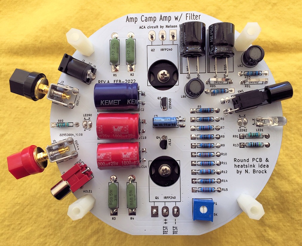
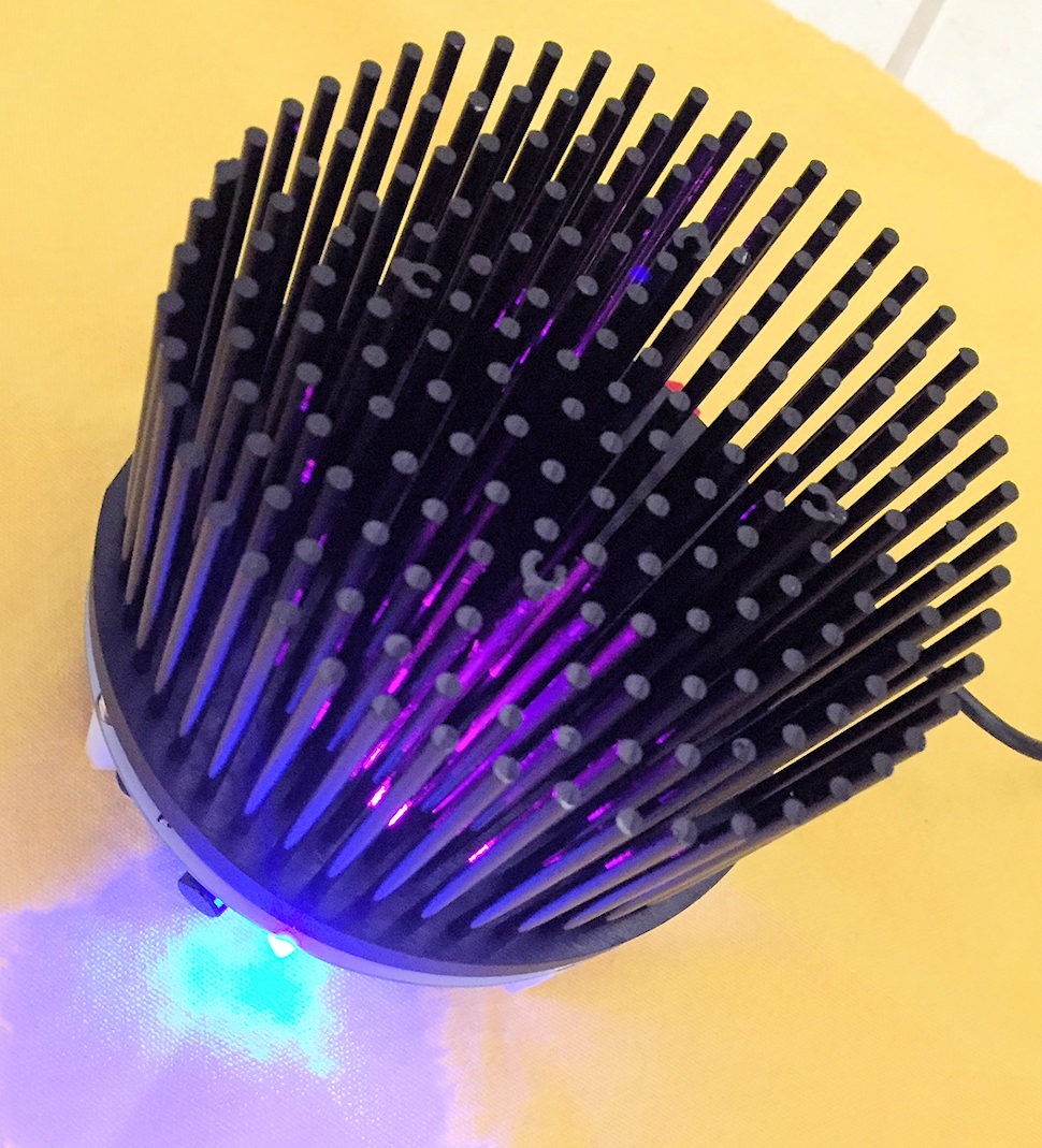
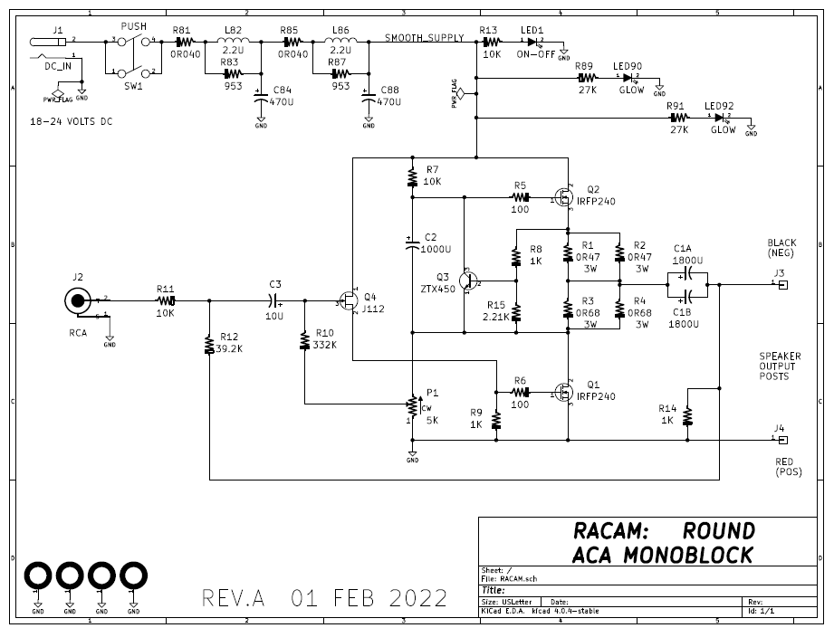
I've been looking through many threads regarding using the P089ZB for the ACA v1.8 build at 24v using the stock meanwell 24V 5a SMPS.Honestly I'm a little surprised that nobody seems to have built an "ACA hedgehog" with premium parts. It has the advantage of being a monoblock so the channel separation is off the charts. And variants have been offered which include a 4 pole LCLC filter right on the PCB, to clean up the power supply rail and attenuate SMPS noise tremendously. (LINK 1) , (LINK 2) .
The on-PCB filter is an exact copy of the SMPS filter currently sold in the diyAudio Store (LINK 3) . The filter is capable of 3 Amps DC and 48 volts DC, so it has loads of safety margin in an ACA monoblock application where the current drawn is less than 2 amps and the voltage is less than 30 volts.
By the way, the Saturday Amp Camp project at the 2022 Burning Amp Festival next month, has attendees building a stereo pair of the Hedgehog amps, sans filter. It remains to be seen whether the provided kits will include Premium Parts or not.
_
It isn't clear if it makes sense to:
1) just keep using the stock SMPS.
2) build or acquire a linear power supply
3) use the P089ZB inline with the stock meanwell 24V 5A
But I do notice that the P089ZB is 3A so might not work or be appropriate?
Thoughts.
You could perform circuit analysis upon the schematic of the ACA With Premium Parts, and calculate how much current each channel draws from the SMPS. If the current is less than 1.5 amperes per channel then a single PO89ZB can supply both channels.
On the other hand, if either (a) the ACA With Premium Parts draws more than 1.5 amperes per channel, or (b) you simply want plenty of safety margin, or (c) you simply want additional channel separation between the left channel power and the right channel power supply,
then
a pair of PO89ZB filters -- one per ACAWPP channel -- perhaps might be a lovely fit for you.
I think I like the idea of a pair of PO89ZB filters, one per ACAWPP channel. That way I won't have to have a separate external box with additional external connections, etc. I will just wire them up inside the existing ACA enclosure.You could perform circuit analysis upon the schematic of the ACA With Premium Parts, and calculate how much current each channel draws from the SMPS. If the current is less than 1.5 amperes per channel then a single PO89ZB can supply both channels.
On the other hand, if either (a) the ACA With Premium Parts draws more than 1.5 amperes per channel, or (b) you simply want plenty of safety margin, or (c) you simply want additional channel separation between the left channel power and the right channel power supply,
then
a pair of PO89ZB filters -- one per ACAWPP channel -- perhaps might be a lovely fit for you.
I saw a post where you recommended the Nichicon caps as the better choice. Any other component upgrades you suggest?
I will order the boards and will test then provide feedback on this forum when complete. I have two ACA v1.8 as I am running them in monoblocks, so I will be able to upgrade one enclosure then can do side-by-side compares.
I don't think anybody has created an SMPS Filter With Premium Parts thread. If you want to do so then I recommend one of the ideas your thread participants might consider, is: Laying out a new and much larger PCB, which can accommodate a greater variety of sub-100-milliohm 1 watt resistor packages, and a greater variety of electrolytic capacitor packages. Perhaps including (gasp!) SMD caps for reduced parasitic inductance and ESR, if you think that might turn out to be beneficial. I doubt that SMD inductors would improve performance very much, but they might be more plentiful on distributors' shelves, thus easier to buy.
Premium Parts might conceivably include 4-terminal capacitors (link to example) but that might require unacceptably large amounts of PCB surgery.
Premium Parts might conceivably include 4-terminal capacitors (link to example) but that might require unacceptably large amounts of PCB surgery.
I wanted to double check and makes sure this is safe.You could perform circuit analysis upon the schematic of the ACA With Premium Parts, and calculate how much current each channel draws from the SMPS. If the current is less than 1.5 amperes per channel then a single PO89ZB can supply both channels.
On the other hand, if either (a) the ACA With Premium Parts draws more than 1.5 amperes per channel, or (b) you simply want plenty of safety margin, or (c) you simply want additional channel separation between the left channel power and the right channel power supply,
then
a pair of PO89ZB filters -- one per ACAWPP channel -- perhaps might be a lovely fit for you.
Before I start the mod, the initial plan was to put two PO89ZB filters in the ACAWPP enclosure, not in parallel, but branched from one Meanwell 24v 5A SMPS to supply one PO89ZB feeding amp1 and the other PO89ZB feeding amp2 in the same enclosure.
----------> PO89ZB ------> AMP1
|
24v 5A SMSP ---
|
----------> PO89ZB ------> AMP2
In simple stereo configuration, I don't see any issues, 'unless' one of the amps failed, then you could have the case of the 5A SMSP, in effect, being connected to only one PO89ZB? Only a real issue if the working amplifier actually draws a heavy current. TBD.
In addition to stereo, the ACA amps can be configured in Mono XLR/RCA Bridged and Mono RCA Parallel so the 'output' from the amplifier could have voltage and amperage gains out of amplifier to the speakers, but that would be the 'amplifier' output to the speakers, and not changes to the voltage/amperage input to the PO89ZBs.
Makes sense to gather the facts/data of the volts/amperage used inside the enclosure based on the various amplifier configurations (i.e, stereo, mono, parallel) and go from there.
Thoughts? Is it safest to wait out the 6A version of the PO89ZB?
As for an extra layer of safety regardless if the ACAWPP amperage pull is below 3A, how about if I added a 3A fuse right before each PO89ZB just to protect the PO89ZB should one of the amp channels fail? The fuse wouldn't be in the sound signal path. So likely no unintended consequences there. Might a fuse add noise to the incoming power, I wouldn't think so, but even if it did, it would likely get filtered in the PO89ZB?You could perform circuit analysis upon the schematic of the ACA With Premium Parts, and calculate how much current each channel draws from the SMPS. If the current is less than 1.5 amperes per channel then a single PO89ZB can supply both channels.
On the other hand, if either (a) the ACA With Premium Parts draws more than 1.5 amperes per channel, or (b) you simply want plenty of safety margin, or (c) you simply want additional channel separation between the left channel power and the right channel power supply,
then
a pair of PO89ZB filters -- one per ACAWPP channel -- perhaps might be a lovely fit for you.
After some testing and measurements, I think I answered my own questions. I think adding two PO89ZBs (one per amp) will work with no safety issues for the v1.8 ACA using the Meanwell 25V 5A SMPS (but I am not an EE nor pretending to be one so you should do your own testing).You could perform circuit analysis upon the schematic of the ACA With Premium Parts, and calculate how much current each channel draws from the SMPS. If the current is less than 1.5 amperes per channel then a single PO89ZB can supply both channels.
On the other hand, if either (a) the ACA With Premium Parts draws more than 1.5 amperes per channel, or (b) you simply want plenty of safety margin, or (c) you simply want additional channel separation between the left channel power and the right channel power supply,
then
a pair of PO89ZB filters -- one per ACAWPP channel -- perhaps might be a lovely fit for you.
Using a power meter measuring the watts used from the AC lines to the Meanwell, the steady state AC watts consumed were 79 watts. What surprised me was regardless of the load or connection type (stereo, mono bridged, or mono parallel) or which speakers I used, the watts stayed consistent at 79 watts which really surprised me. It’s like the ACA v1.8 draws what it does, regardless of load, connection type, or speakers being used. The conclusion I drew was: this is a class A amp, always on, full power regardless of the load, hence all of the heat even if it isn’t playing anything. To me, this is good in that I am now dealing with consistent numbers and apparently no meaningful variability in watts/amperage used.
I know that Watts = volts * amperage.
So, amperage = watts / volts.
According to the Meanwell 24V data sheet, the P1M version of the power supply (which is what ships with the kit) is 89.5% efficient.
Amperage_used_total = (79watts * .895 efficiency) / 24 volts = 2.9A
Looks like the ACA draws a total of 2.94A for both amplifiers. I suppose if one wanted to use the conservative case, you’d assume that the Meanwell power supply was 100% efficient, which it isn’t, as spec implies 10.5% of watts are converted to heat, but just for argument’s sake:
Amperage_used_total = (79watts * 1 ) / 24 volts = 3.29A
Either calculation means, that using one PO89ZB for the entire unit would be edging close to the design spec of the MAX rated amperage of the PO89ZB at 3A.
But using one PO89ZB for each amplifier means that each amp would only draw between 2.9/2 – 3.29/2 amps, or 1.45A – 1.64A each, well within the design spec of the PO89ZB.
Last edited:
Rthatcher has a nice board for a filter that works really well. Lot's of us have used it and the sound improvement is significant. I can be configured dual mono or stereo.
The common thing here has been to stay with a single 24v Meanwell and add the rthatcher filter, go to dual 24v Meanwells with the rthatcher dual smps board. I have made modifications to use dual 36v Meanwells with the FQH44N10 transistors and the rthatcher board and it sounds amazing. I do think that building a dual mono linear power supply could really bring out the best in this amp and that is my next step.... once I figure out how I am going to do it?!?!?I've been looking through many threads regarding using the P089ZB for the ACA v1.8 build at 24v using the stock meanwell 24V 5a SMPS.
It isn't clear if it makes sense to:
1) just keep using the stock SMPS.
2) build or acquire a linear power supply
3) use the P089ZB inline with the stock meanwell 24V 5A
But I do notice that the P089ZB is 3A so might not work or be appropriate?
Thoughts.
The common thing here has been to stay with a single 24v Meanwell and add the rthatcher filter, go to dual 24v Meanwells with the rthatcher dual smps board. I have made modifications to use dual 36v Meanwells with the FQH44N10 transistors and the rthatcher board and it sounds amazing. I do think that building a dual mono linear power supply could really bring out the best in this amp and that is my next step.... once I figure out how I am going to do it?!?!?
https://www.diyaudio.com/community/...supply-filter-kits.376245/page-9#post-7162753Rthatcher has a nice board for a filter that works really well. Lot's of us have used it and the sound improvement is significant. I can be configured dual mono or stereo.
Here is what I ended up doing with the P089ZB and the ACA V1.8 with premium parts and a single 24V power supply. Because the P089ZB is passive it took .2 volts of power. The "In" voltage was 24.7 and "out" voltage was 24.5 from the P089ZB . The only mod I did to the P089ZB was to use the Nichicon 470uF 50V caps instead of the stock caps.
It was a fairly easy mod, the P089ZB boards and parts are only a few bucks apiece. And the improvement was subtle but there. The sound was cleaner and less processed sounding, not sure how else to describe it.

It was a fairly easy mod, the P089ZB boards and parts are only a few bucks apiece. And the improvement was subtle but there. The sound was cleaner and less processed sounding, not sure how else to describe it.
I might suggest a 2.2uF, 50V Nichicon ES series bipolar cap in the C3 position, though I have continued to use the 10uF Elna Silmic II that was part of the original kit.
I'm interested in updating my own ACA pair that I use in balanced mono configuration but was interested to see edthomp's post here about his frequency response measurements. Specifically the reduction of HF response starting at about 12kHz. Those measurements match the sound I am hearing in my own system. I swapped in an alternate amp and the highs returned so it's likely not my room or ancillary equipment.
I'll do the original Tungsten updates, but would updating and increasing/decreasing the value of C3 and/or C4 give better HF response?
Thanks!
- Home
- Amplifiers
- Pass Labs
- ACA amp with premium parts