Hello all .. in one of my postings I talked about an IMD problem of the KEF LS50 speaker measured by someone in the ASR forum .. but the reason of the problem is not clear ... many pics further down the thread :
https://www.audiosciencereview.com/forum/index.php?threads/kef-ls50w-ii-measurements.36932/
Bjoern Idland of SEAS once measured strongly induced (harmonic) distortion between tweeter and woofer cone in one of their 18cm coax drivers , so maybe the same mechanism works for IMD too!?
Maybe a major drawback for 2-way coaxials regarding coloration and resolution .
bye
LS50 is a midwoofer/tweeter coaxial. NOT ideal.
Only handful in the market like TAD’s or KEF’s. Like Reference Meta coax, or 2018 R series coaxial a close second.
Or something else. @5th element who’s cracked the code to coaxials; like Purifi’s cracked the code for high excursion midwoofers.
😉
TBA. 🤞🏻
Only handful in the market like TAD’s or KEF’s. Like Reference Meta coax, or 2018 R series coaxial a close second.
Or something else. @5th element who’s cracked the code to coaxials; like Purifi’s cracked the code for high excursion midwoofers.
😉
TBA. 🤞🏻
Last edited:
Okay, and the position of the microphone?14 liter sealed for all
SPL is at tested frequency and all speakers are in a closed box with the same volume.
I can already see some potential problems here in sense of excursion and the like, as well as the interaction (because of this) with the cabinet.
Some speakers will naturally have a much higher output at a certain frequency, because of the Qt of the speaker as well as the Fs for example. This effect is heavily amplified by the cabinet.
So based on how this experiment was done, I already have my doubts about the validity of the results to be perfectly honest, I am sorry.
First of all, no cabinet to begin with (that way you also limit any other issues)
Second is to determine a fair and equal reference point for the sound pressure levels.
Conditions are stated in all the individual Test groups, as linked directly by Shrub0.
Those having challenges following links here they are stated
“Testing condition are as follows: The test enclosure is a .5 cu ft (14 liter) sealed box with the bottom lip of the speaker just 2 inches above the floor. The microphone is on a stand 49"high with the base of the microphone 33" from the driver. A distance of about 1.5m from the speaker to the microphone. As I'm not measuring in an anechoic chamber my measurements are not comparable to anyone else's but comparisons can be made between the drivers I test.”
All other tests available online
1. use tests in free air (magnet rigidly mounted)
2. In a test box of specific dimensions, depending on the size of the woofer (eg. Voice Coil test bench)
3. On a large eg. IEC baffle
4. On very large baffle closely approximating infinite baffle.
There are pro and cons of all tests methods.
Many of the test results don’t give good data for mid bass (<252Hz) or bass response (<100Hz)
The external validity of the test results is questionable. That is, because the conditions aren’t the same, the tests results can’t be compared directly to others. But Mark’s aware of this.
But the internal validity is high: results from the same test conditions can be compared with a high degree of confidence.
I, like many other, like the fact that you have almost 20 midwoofers, and counting, compared in a 14L cabinet.
The next time I’m looking for a woofer that suits a 1/2 cu foot sealed cabinet, i know where there’s good data as a comparison point. Without having to buy and test 20 woofers.
Anyway, we’re getting increasingly off topic.
Anyone got any comments about the aluminium PTT drivers?
In the house!
Attachments
Last edited:
I don't think we are getting offtopic at all!!!
Discussing the validity of results is the main thing in any set of experiments, especially when people claim certain results.
So when people claim certain results, this is highly ontopic actually.
The fact that people already say that they directy trust these results and "know where there’s good data as a comparison point", says enough.
I have my doubts about it, quite heavily actually. I don't agree the internal validity is high.
Btw, that doesn't have anything to do with the intentions or time/effort put into something.
Btw 2, it can never be expected that readers have to go through a maze of text to find out the measurement conditions.
These should be easily accessible in the describing text or just stated before the results to prevent any kind of confusion or certain expectations.
Last edited:
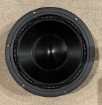
Beautiful driver. I wonder what is the function of the increased thickness of the foam (?) around the periphery of the cone. Damping, perhaps?Conditions are stated in all the individual Test groups, as linked directly by Shrub0.
Anyway, we’re getting increasingly off topic.
Anyone got any comments about the aluminium PTT drivers?
In the house!
B_force this will my last post on this thread regarding my testing, feel free to offer more critiques on the individual testing threads that I've already linked.Okay, and the position of the microphone?
The measuring conditions are in the very first post of the testing thread for example in the 10" test here: https://www.diyaudio.com/community/threads/10-woofer-subwoofer-imd-comparison.391184/#post-7146063
The reason I choose mounting the drivers in a sealed box is that this presents a possible use case. I don't think anyone would choose to run a 6.5" driver on an open baffle and expect it to play relatively loud (for example 85 db) at 40 hz. Granted most people end up with vented enclosures, but that would be a logistically nightmare to provide a fair tuning for all. Most drivers will have lower distortion in a sealed box at the impedence peak so this one of the reason I ran my tests at many different frequencies. I also choose to have the driver sit very close to the floor to minimize floor bounce cancelation.
I'm sure it's not a perfect test but I try to answer everyone's questions about it so that the reader can decide if it's valuable information to them. Also I have no business connections with any of the manufactures. I only have sent messages asking technical questions to some of them and are thankful that they have taken the time to respond.
B_force you still haven't answered my questions, like how could the spreadsheet present the data more clear and what missing drivers are there. "He has a right to criticize who has a heart to help." --Abraham Lincoln

I do.I don't think we are getting offtopic at all!!!
Discussing the validity of results is the main thing in any set of experiments, especially when people claim certain results.
So when people claim certain results, this is highly ontopic actually.
The fact that people already say that they directy trust these results and "know where there’s good data as a comparison point", says enough.
I have my doubts about it, quite heavily actually. I don't agree the internal validity is high.
Btw, that doesn't have anything to do with the intentions or time/effort put into something.
Btw 2, it can never be expected that readers have to go through a maze of text to find out the measurement conditions.
These should be easily accessible in the describing text or just stated before the results to prevent any kind of confusion or certain expectations.
I'm sure we'll all look forward to seeing your own IMD tests, or indeed, any data you have to contribute. Perhaps you could start your own thread about how to properly conduct IMD testing and post them there. Or if you have measurements of the aluminum purifi drivers, post them here. Comparative measurements would be particularly welcome.
The reason why I am delivering critique here, is because you used it as an argument on multiple posts to me and others.B_force this will my last post on this thread regarding my testing, feel free to offer more critiques on the individual testing threads that I've already linked.
The measuring conditions are in the very first post of the testing thread for example in the 10" test here: https://www.diyaudio.com/community/threads/10-woofer-subwoofer-imd-comparison.391184/#post-7146063
The reason I choose mounting the drivers in a sealed box is that this presents a possible use case. I don't think anyone would choose to run a 6.5" driver on an open baffle and expect it to play relatively loud (for example 85 db) at 40 hz. Granted most people end up with vented enclosures, but that would be a logistically nightmare to provide a fair tuning for all. Most drivers will have lower distortion in a sealed box at the impedence peak so this one of the reason I ran my tests at many different frequencies. I also choose to have the driver sit very close to the floor to minimize floor bounce cancelation.
I'm sure it's not a perfect test but I try to answer everyone's questions about it so that the reader can decide if it's valuable information to them. Also I have no business connections with any of the manufactures. I only have sent messages asking technical questions to some of them and are thankful that they have taken the time to respond.
B_force you still haven't answered my questions, like how could the spreadsheet present the data more clear and what missing drivers are there. "He has a right to criticize who has a heart to help." --Abraham Lincoln
As this topic is about Purifi speaker (see topic titles), this is most definitely relevant!
Therefore I simply have the right to have my counter argument to it.
Although the idea of practical use cases seems a good idea, this very often leads to (very) skewed results.
The idea of comparing units is NOT about a practical use-case, but is all about getting proper and objective data.
I have no idea why many hobbyists seem to keep in this kind of mindset?
Especially when certain claims are being made, it's the responsibility of everyone to find out if those claims are objective or not. Just assume certain results will result in misinformation and eventually maybe in (unintentional) false believes or disappointment.
I am totally fine when results "are not perfect", but I am not fine when people respond with these results like an argument or "have proof".
Because in that case it really DOES matter how things are being measured and compared.
In that case it also NOT up to the reader to "decide", because information is presented already in a biased way.
Second, you are moving into a territory that I know a thing about or two.
Especially when results don't seem to line up what's being expected from the literature.
So, no I wont start my own threat as long as people keep posting argument, information, measurements or data that isn't objective or won't give a neutral and objective picture. This is perfectly 100% on topic, since the argument was made in this topic (NOT by me btw!!).
Audi alteram partem!
Or in other words, you can't just bail out after dropping some statements, data or claims and when some people disagree with those!
That is literately how discussions go.
It's not just one street monologue for people who only agree with things.
Unfortunately that seems to be more and more the standard these days.
Which at this points makes me very confused about the intentions here?
Because I get sometimes a VERY strong feeling that it's not about being neutral and objective anymore and to look for the best possible implementations of certain parts, products, speakers etc.
To answer your last question, all the points above is already an answer to that.
Briefly explain what has been measured, why, how and where.
Giving data in graphs also really helps etc.
But all of that is of no use if the test method is already very debatable to begin with.
b_force> shrub has standardized on the basis of SPL. The two tones are the same SPL. Within the pistonic passband, this should result in good basis on which to compare. Do you have another basis that would be better than this? I've used excursion at the low frequency tone before, but this means results are only directly comparable to drivers with the same diaphragm area. Which is useful in some ways, but at the end of the day, we always want to know how a driver behaves at a certain SPL, regardless of size.
I also don't care much for using a boxed speaker. But I think even Klippel does it this way, so what do I know. Also, because of how distortion squiggles around a bit, I no longer would do typical multitone testing any longer. Random chance alone means you unfairly help or hurt a driver by the tones you pick just happening to be where the driver response zigs or zags. In the future I would use a low frequency tone to set driver excursion, then use a sweep. I don't think Soundeasy will do this, if anyone has suggestions I'd like to know. You need to be able to calculate HD and IMD as it's sweeping and plot that. Erin started doing this with his Klippel.
I also don't care much for using a boxed speaker. But I think even Klippel does it this way, so what do I know. Also, because of how distortion squiggles around a bit, I no longer would do typical multitone testing any longer. Random chance alone means you unfairly help or hurt a driver by the tones you pick just happening to be where the driver response zigs or zags. In the future I would use a low frequency tone to set driver excursion, then use a sweep. I don't think Soundeasy will do this, if anyone has suggestions I'd like to know. You need to be able to calculate HD and IMD as it's sweeping and plot that. Erin started doing this with his Klippel.
Thanks for the feedback Augerpro,
But wouldn't the low tone you choose to set the excursion favor some drivers? Depending on where along the impedence curve the low tone is.
As current is a factor in distortion according to klippel and higher impedence means less current for a given spl.
Not saying my way is the best, there is probably pros and cons to each testing method but choosing many different low tones makes sense to me. I also like what Joseph Crowe is doing with a multitude of tones all at once but I just wish the bass was equalized so It could be compared with a driver of different low end roll off. https://josephcrowe.com/blogs/news/sb-audience-bianco-15ob350-15-open-baffle-woofer
Last edited:
That's a great point shrub, I should have mentioned it. I would go with a frequency that is lower than Fs for all drivers. Where their impedance has dropped to steady state. Something like 20-30hz. Driver response this low will be quite different, so that may change whether you use SPL or excursion to standardize, or possibly accept you can no longer compare directly across driver sizes. Or perhaps above Fs, say, 100 hz, where most drivers we are looking at would be getting to the flat area of their passband, so you could standardize by SPL. But I'm afraid it would take a lot of current for some drivers to reach the excursion required to characterize BL(x) and IMD behavior, so that might have more negative tradeoffs than 20hz.
note that the small sealed box raises the resonant frequency and causes a large back pressure on the driver. This means that more current is needed for the same SPL for the tones below the resonance (stiffness controlled and stiffness being very high). The higher current provokes more Bl modulation (force factor modulation) and the higher back pressure causes high Sd modulation. Both mechanisms increase the wide band IMD (act as a gain modulation ). The small sealed box is a very realistic condition but will provoke more IMD compared to the standard data sheet conditions (infinite baffle)
note that the small sealed box raises the resonant frequency and causes a large back pressure on the driver. This means that more current is needed for the same SPL for the tones below the resonance (stiffness controlled and stiffness being very high). The higher current provokes more Bl modulation (force factor modulation) and the higher back pressure causes high Sd modulation. Both mechanisms increase the wide band IMD (act as a gain modulation ). The small sealed box is a very realistic condition but will provoke more IMD compared to the standard data sheet conditions (infinite baffle)
Thanks for the feedback! What would you do for this sort of distortion testing? I am specifically interested in understanding FFM because this is one distortion mechanism that I know for sure I've heard many times.
shrub> when I've done this testing in the past I've mounted the drivers free-air on a large baffle. And my mic distance was around 14" I think.
I try to be pragmatic about these things. At the end of the day do you choose your cabinet size first or your driver first? And I think as a designer it’s the former. As a dabbler/DIY it’s the latter.
So If I were to do in-box testing I’d set and build standard cabinet sizes with replaceable front baffles.
Eg.
1/32 cu ft - 2”
1/16 cu ft - 3”
1/83.5L- 4”
1/4 cu ft 7L: 5”
1/2 cu ft- 6-7”
1 cu ft - 8”-10”
2 cu ft - 10”-12”
4 cu ft - 15”-18”
6 cu ft- 18-21”
Of course they need to be equalised to give the same response under 100Hz.
If the driver is grossly mismatched to the box eg. needs larger or smaller box- move it to larger or smaller box.
It’s a balance of trade-offs-
More boxes to build- But makes it fairer for sizes of comparable sizes. A 10” might be the limit for a 1/2 cu ft box; but only because both XXLS and L26Roy are designed for it. I wonder what happens if you put in a Deltalite 10 into 1/2 cu ft. Or a 6” subwoofer in 1/4” ft eg. SONOS subwoofer. Clearly that hasn’t been a problem for the market- they probably shifted more subwoofers than anyone else…
But it’s a lot of work. You probably need helpers.
It may yield some, err, interesting results; like what happens when you put a large driver in a ridiculously small box and turn up the EQ:
https://www.mfk-projects.com/Blog/Ranting/subwoofer.html
On the other hand, If you want to dispense with building boxes then compare groups on a very large baffle. Again replaceable inserts.
Eg. 6-7” group comparison.
Still, a lot of work.
Then it’s up the DIY to implement their own box. (BR, PR, BP etc)
Whatever you do Mark, I appreciate it. Could your tests be refined? Sure.
The worse data is completely misleading data. And I don’t think you have that….
Last edited:
Thanks for the knowledge and feedback guys. I guess the main reason I choose the sealed enclosure is because I already had one and most of my designs end up to be sealed. Plus I do a week listening session and break in session for each driver and have a lot of fun listening to the driver full range and with a low pass and sealed is a good way for me to listen to the driver (not the port). Front loaded horns are another favorite but are a big chore to get the drivers in and out. I’ve tried ported,6th order vented and passive radiator and to me the these alignments add quantity of bass but not quality.
I think a baffle wall would be nice but I don’t have a spot for one. I’m thinking dipole would present some problems as well, for example wouldn’t some out of phase tones wrap around the baffle and cancel others out unevenly?
I think a baffle wall would be nice but I don’t have a spot for one. I’m thinking dipole would present some problems as well, for example wouldn’t some out of phase tones wrap around the baffle and cancel others out unevenly?
Yes, that is where a big baffle and closer mic placement help.I think a baffle wall would be nice but I don’t have a spot for one. I’m thinking dipole would present some problems as well, for example wouldn’t some out of phase tones wrap around the baffle and cancel others out unevenly?
Hello All,note that the small sealed box raises the resonant frequency and causes a large back pressure on the driver. This means that more current is needed for the same SPL for the tones below the resonance (stiffness controlled and stiffness being very high). The higher current provokes more Bl modulation (force factor modulation) and the higher back pressure causes high Sd modulation. Both mechanisms increase the wide band IMD (act as a gain modulation ). The small sealed box is a very realistic condition but will provoke more IMD compared to the standard data sheet conditions (infinite baffle)
Given a sealed enclosure there is a range of tiny to huge. The smaller the sealed air volume the greater the Total Q of the composite of the driver and enclosure.
Designing a sealed enclosure often the design goal is Total Q is equal to 0.707, kind of a Goldie Lox value, not to small or not too large but just right.
I am not speaking equalization to maintain a constant current. I am talking constant voltage output from the amplifier. The enclosure pressure increase will flatten as the current falls. The bass (below 2 * Fs) Frequency Response will also taper off some.
I tested this. I installed a 6-1/2inch Purifi driver in a sealed 0.55 cubic foot Denovo enclosure.
As expected the 2nd HD below 100hZ increased a bit. The HD above 100hZ was largely unchanged. The Two Tone 50hz , 425hZ IMD was unchanged or slightly improved. Voice Coil displacement is reduced.
Question to Lars;
Why are you equalizing to maintain constant current or Frequency Response below resonance.
See the attached test plots:
Thanks DT


Last edited:
One idea would be to at least make everything equal with something like a Linkwitz Transform.b_force> shrub has standardized on the basis of SPL. The two tones are the same SPL. Within the pistonic passband, this should result in good basis on which to compare. Do you have another basis that would be better than this? I've used excursion at the low frequency tone before, but this means results are only directly comparable to drivers with the same diaphragm area. Which is useful in some ways, but at the end of the day, we always want to know how a driver behaves at a certain SPL, regardless of size.
I also don't care much for using a boxed speaker. But I think even Klippel does it this way, so what do I know. Also, because of how distortion squiggles around a bit, I no longer would do typical multitone testing any longer. Random chance alone means you unfairly help or hurt a driver by the tones you pick just happening to be where the driver response zigs or zags. In the future I would use a low frequency tone to set driver excursion, then use a sweep. I don't think Soundeasy will do this, if anyone has suggestions I'd like to know. You need to be able to calculate HD and IMD as it's sweeping and plot that. Erin started doing this with his Klippel.
The downside is that it only works well when the REAL TS parameters are determined.
(Or at least the Fs, Re, Qts etc).
Although I don't expect it to be an issue for higher-end speakers (I have most definitely seen exceptions), some speakers just don't line-up with the TS from the datasheet.
Which is critical to get the Linkwitz Transform right.
But that's the only way to get all lower frequency response the same.
However, it's still not perfect, some speakers, especially subwoofers, roll-off much quicker because of higher Le.
This will have an effect on the higher harmonics.
Also, there will be a difference in how much power a speaker needs.
Or to be more specific, the VA curve (power over frequency).
You do point out a very important point with Klippel measurements.
Klippel assumes that the Cms and Rms are constant over the whole frequency range.
It won't take you very long on Google Search, to find out that it's not true at all.
(Novak has some excellent papers on this)
Second important point you're making, below the the Fs, the distortion rises drastically.
So even if all responses will be flat, it really matters were the Fs will be.
This is one of the reasons why a closed box doesn't work so well, since the Fb is shifted up.
You also introduce more variables into the equation.
In the end measuring things can be fun and all, but if we don't really know what's going on, the numbers you're gathering don't say anything at all. Even less so when they don't seem to follow what would be expected from literature.
This is also the most dangerous part about "just doing some quick measurements".
Because it might look something promising, but without knowing what is really going on, it's extremely easy to fall into wrong conclusion. Very often this unintentionally, but it happens nevertheless.
It's also very important to do first some literature research.
What are the expectations and what other research has been done?
Bigger speakers having higher IMD numbers compared to smaller speakers just don't make a lot of sense.
- Home
- Loudspeakers
- Multi-Way
- New aluminum-cone Purifi drivers