Thanks to all. Those days I need to solve some plumbing issues at home. Else the waterfall drawing pics will be at the kitchen... ☹️
Some of the popular MW stations here didn't even bother to use FM but are on the web for better (than MW) audio quality: a search for "Festival 1540" and "Radio Mensabe" will confirm that. Hence Osvaldo's intent for a 200 KHz might be the better alternative, as the AFC could be used for frequency feedback: less distortion and able to deal with higher modulation index.Nowadays it is exactly the way you were used to, at least in Germany, where AM vanishes silently. One has to carefully pick FM stations without annoying charts fodder and babbling presenters.
Best regards!

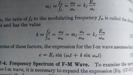
Please, enlight me a bit. In the well known books, m is the modulation index for AM systems, with 0<m<1 or 100%. Which is the mean you are using m here?🤔
If you're refering to MW: MW in Germay is acronymous for Mittelwelle, the same as AM in USA, e.g.
Btw, AM also abbreviates amplitude modulation, hence also is applicable for long wave (LW) and Kurzwelle (KW)/short wave (SW) broadcasting. US English isn't overly exact here.
Best regards!
Btw, AM also abbreviates amplitude modulation, hence also is applicable for long wave (LW) and Kurzwelle (KW)/short wave (SW) broadcasting. US English isn't overly exact here.
Best regards!
Short and simple definition @ https://www.rfwireless-world.com/Terminology/What-is-modulation-index.html
In FM broadcasting, m is referred to the highest audio frequency, 15 KHz.
In FM broadcasting, m is referred to the highest audio frequency, 15 KHz.
Thanks guys. I got it! This pics are from Seely's book, hence my confusion
Attachments

Last edited:

Now that the plumbery trouble is solved, l'll try return to the project. For the proper adjustement of the IF band width, which is the best way?: including or not the detector itself. Stage by stage or a global overall curve?
In your case the proper coupling between primary and secondary of the IF transformers has to be set up as well. That would be fairly easy with a spectrum analyzer but it's hard without. Without access to such an instrument, the IF transformer of each stage has to be set to critical coupling, starting with the first and in a way that the instrument used (input R, C) does not influence measurement. One way to do that is to load the anode LC with an R of low value so that LC doesn't affect alignment of the stage's input bandpass filter. Although this works well to set up critical coupling, there's no clue to bandwidth other than listening and or observing AM of the envelope. In case the bandwidth is much too low, coupling between coils has to be increased and load (damping) resistors decreased. When (being lucky) bandwidth for several stations is OK but too low for others by no more than a factor of ~2, consider frequency feedback.
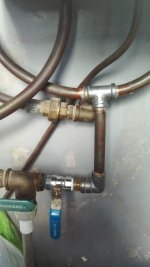
I was thinking to proceed in a way like the calibration procedure for TV IF's: load the last IF primary with low value R (I use 680R) and decoupling with 470pF. A temporary AM detector using germanium diode and low pass RC filter (47K & 220pF). Thus, exciting the last IF grid with the sweep oscillator and adjust couplings and retuning slugs until the proper IF profile is found. Thus, proceed similar going back to the first trafo. This morning I tryed this way and seems to be promisory. As always, suggestions are welcome.

Detector probes are obsolete for VHF in my opinion. They were a solution to the low test equipment bandwidth of the day. I haven't used one in decades. Just do what you said, damp the primary, inject at the previous grid, probe at the limiter's AGC point (after the first resistor), tune the secondary: then damp the secondary, tune the primary; then move back a stage, leaving the scope probe where it is. Continue until well done.
This morning I did some tests. Using the detector probe something like the above depicted gave good results. Hooking it at the last IF traffo, but using 470pF decoupling cap; a 680R damping resistor a 1N60 diode and paralelled 270pF and 47K as diode load, to the oscillo input and using the EICO 368 as generator, I was able to fix the 200KHz IF BW not withouth arduous labor. But as the physical layout is really unstable, l will need to redo the project in a more stable form.
But as I received some HF ham radio to repair; so momentarily I need to suspend the project by some time.
But as I received some HF ham radio to repair; so momentarily I need to suspend the project by some time.
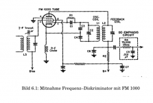
The article is in German but some of the diagrams are copied from a US source. Link to the pdf:
https://doczz.net/doc/5776691/fm-demodulation---ing.-dietmar-rudolph
https://doczz.net/doc/5776691/fm-demodulation---ing.-dietmar-rudolph
According to the article, it's injection lock with the oscillator running at a subharmonic of the IF, because having it run at the IF itself would cause problems due to coupling to the IF amplifier.
Running the oscillator at a harmonic would be the better solution as the tuned IF wouldn't be affected by it. The FM1000 datasheet is only available at the radio museum for members so no idea what the limits of the tube are.
- Home
- Source & Line
- Analogue Source
- A new FM tuner with Compactron Tubes