By now it is two-fold learning; how to wind, and what to wind. Somewhere I have the details for two that have worked very well for me. The 20-20 S-265-Q, and the 20-20 Plus S-271-S. 10k a-a/40W and 5k a-a/80W respectively.
Bi-filar has more than one use; for a secondary, two wires in ||, but needing fewer turns per layer allow a thinner layer that takes up the whole length of the layer.
cheers,
Douglas
Bi-filar has more than one use; for a secondary, two wires in ||, but needing fewer turns per layer allow a thinner layer that takes up the whole length of the layer.
cheers,
Douglas
Last edited:

They both have 22 layers of primary interleaved between three layers of secondary on each side. That makes for a SSS-P22-SSS configurationImpressive! Anyway, what's the difference between both configs? I just can't get the abbreviations sorted...
Best regards!
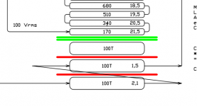
The first transformer starts with a consecutive winding. The anode starts at the bottom, then 22 layers are wound. The B+ layer is the top primary layer.
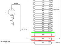
The second transformer however has its anode layer placed in the middle. And all anode layers have free separate connections end. You then start connecting them with voltage gradient dropping from the center progressively to the ends. This is why I called it snail primary - it reminds of the progression of the inner center to the outer ends. Basically in the end by doing this, you increase primary clumped capacitance by a factor of 4, but have decrease the bottom P/S capacitance by 205 times in this situation.
This technique is useful when designing high leakage inductance transformers, where you need to be careful with P/S capacitance. One P/S capacitance bridge is not really problematic, but two and above can become so. while clumped primary capacitance is less problematic. In this example, I have moved the resonant frequency 2x times above the audio range.
I'm writing some documents on this, but still in the beginning and I don't know when I will be ready with some textbooks, but here's a rough pdf document I managed to put together quickly and put some calculation examples. The interleaving is from Transformer 1.
In this case,
would it have been better to make a
P s P K s P K s P instead of s P s K P K s P s
differentiate the thickness of the insulation (for exemple) 0.8 anode side to 0.3 +HT side, between P and S and 0.2 between K and S
I created an Excel page to calculate and balance the capacity of each interface.
50AE
You said that résistance of each S must be équal.
What's happen when some of S are in parallel strapping for 4 or 8 for exemple and all of them are employed
Yan
I kind of need to put my words back first. What I thought what was secondary resistance actually when progressing into my research is more probably caused by capacitance distribution. Especially when you connect secondaries in series. What I thought was resistance would just move the resonant frequency of that Cs/Ls dip, but back then I didn't have equipment above 100kHz + to test that further.
Parallel secondaries are you safest bet to not stir up a beehive. When you need to connect them in series, for most cases best performance happens by cross coupling. Cross-coupling equalizes Rdc as a bonus, but also can distribute capacitances more favorably.
Examples:
For an interleaving of S-Px-S2-Px-S2-Px-S, which has two outer secondary layers of 1/2 turns and two inner secondaries of 1/1 turns. The primary packages of Px have an equal amount of turns and layers.
What you want to do is parallel the inner and outer S secondaries as ONE package and parallel the inner S2 secondaries as the second package. That could be your 1R and 4R packages.
Here are some rules of thumb I discovered empirically.
1. You can go in series secondaries when the capacitance difference between the two P/S bridges is small or close to none. Avoid series connecting secondaries capacitively interconnected with high leakage primary packages. This is especially problematic for Double Coil transformer and you need to be very careful there.
2. Go with parallel secondaries where there is a very high capacitance difference and a long physical distance between the two P/S bridges.
3. Definitely start with single coil transformers. They are much more forgiving to mistakes than double coil ones.
Going for PP instead of SE will also change the game, because logically, it gives entirely different capacitances. PP offers the huge benefits of having intrinsic capacitance equality of halves
Attachments
Last edited:
I "found" the core lamination (see pic) on my shelf, and have wound a PP output transformer with 20:1 turns ratio, 60 mm packet thickness. One layer is 0.35 mm. Unfortunately I had no information on the characteristics of the core material. It is a homogenous grey iron, without any visible crystal domains. It looks "better" than common mains transformer laminations, that I also have in the same size, and the crystal domains are visible there. Also the color is different, not so smooth grey.
Has anybody any idea, if it is suitable for the purpose? Actually it works well, but since this is my first and only output transformer design, I can't compare with any other.
Has anybody any idea, if it is suitable for the purpose? Actually it works well, but since this is my first and only output transformer design, I can't compare with any other.
Attachments
As the I and the long E parts, where the magnetic flux lines are perpendicular to the bobbin axis, are wider than any other part, I guess these laminations could be grain orientated.
Best regards!
Best regards!
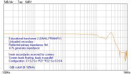
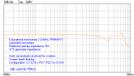
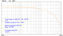
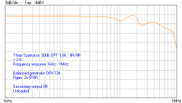
Some more measurements of transformer 2.
Attachments
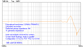

Why unloaded measurments?Some more measurements of transformer 2.
I always like to measure unloaded for studying purposes, where loading can mask resonances with its roll-off.
For those interested in a arduino controlled winding machine
https://www.diyaudio.com/community/threads/diy-voice-coil-winding-machine.320505/page-5
Hi 50AEI'm writing some documents on this, but still in the beginning and I don't know when I will be ready with some textbooks, but here's a rough pdf document I managed to put together quickly and put some calculation examples. The interleaving is from Transformer 1.
The secondary layers close to primary layers with double green lines, it seems not to connect any other wire. Used as a screen for sheding capacitance?
Best regards!
Andy
Attachments
Hi all, 50AE
Many thanks for your explanation.
Very clever
This method is suitable for high Z with few interleaves or T I.
Best regards
Yan
Many thanks for your explanation.
Very clever
This method is suitable for high Z with few interleaves or T I.
Best regards
Yan
Yes, the unconnected layers where dedicated for screens and the main purpose of this educational project was demonstrating the influence of screen windings and their connections.
Best regards to all!
Best regards to all!
Dear 50AEYes, the unconnected layers where dedicated for screens and the main purpose of this educational project was demonstrating the influence of screen windings and their connections.
Best regards to all!
The hottest secondary relative potential = Pl/Sl =22/4, which is 5.5, 2.353 is sqrt root of 5.5. How do we calculate this?
Best regards!
Andy
Attachments
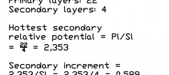
My bad on this one. It's not supposed to be 22/4, but 22/9,35, which is the primary layers divided by the turn ratio. That makes for 2,353 being your hottest secondary relative potential.
Nothing changes, the 200Vrms is there to remind the highest voltage swing happens at the anode.
Thanks! I reviewed the RDH4, Mr. Turner's articles, and your example, now I beginning to understand.Nothing changes, the 200Vrms is there to remind the highest voltage swing happens at the anode.
If I removed the screen wires between P/S, instead of nomex paper and keep the same thickness as the screen wire. The same result?
Best regards!
Andy
i measure one transformer with a 1K source, loaded with 8 Ohm and the same unloaded. See the differance.I always like to measure unloaded for studying purposes, where loading can mask resonances with its roll-off.
Transformer loaded wit 8 Ohm
Same transformer with no load ( just the probe 1:1 100pF)
Last edited:
Well yes, you see the difference for yourself. Loading causes changes of peak and dip resonances amplitudes. Usually the dips get worse and the peaks get damped with loading.
But I like that the dip gets worse and that the peaks are dampened.
For SE without feedback it is not a big problem, usually the tube designs are so "bad" that no frequency above 100 kHz would hurt. Which in most cases is an advantage. In more complex designs with FB, it's totally different.
For SE without feedback it is not a big problem, usually the tube designs are so "bad" that no frequency above 100 kHz would hurt. Which in most cases is an advantage. In more complex designs with FB, it's totally different.
- Home
- Amplifiers
- Tubes / Valves
- Winding my own output transformers...dumb idea?