Check that one of the resistors is not cracked. I had a hell of a problem on another board I was doing because of this. I would just replace the resistor where you are seeing this issue and see if that fixes it
(your voltages for the front end all look good)
(your voltages for the front end all look good)
Hello Bonsai,
I'm thinking of replacing the OPA1641 by OPA1611 or AD797 as these seem supperior in every aspect. What were the reasons that make you chose OPA1641?
Also did you do measurement to compare LSK389B with JFE2140?
I'm thinking of replacing the OPA1641 by OPA1611 or AD797 as these seem supperior in every aspect. What were the reasons that make you chose OPA1641?
Also did you do measurement to compare LSK389B with JFE2140?
The mods have kindly opened up the first post in this thread to enable links etc to the audioXpress documents. Any questions please feel free to ask.
Charlano, The OPA1641 devices are JFET input opamps. The AD797 and the OPA1611 are a bipolar input opamps. The AD797 may require additional compensation to work correctly in this application - so it is not a drop in replacement. Its also a very expensive part to put into a preamp where in this specific application, it offers very little or no benefit. Its best suited to applications with low source impedances and where high gains are required.Hello Bonsai,
I'm thinking of replacing the OPA1641 by OPA1611 or AD797 as these seem supperior in every aspect. What were the reasons that make you chose OPA1641?
Also did you do measurement to compare LSK389B with JFE2140?
The OPA1641 is the best general purpose JFET input audio audio grade opamp so that's why I chose it - very low distortion, low bias current, low supply current and good PSRR (ADI also make some great high performance JFET input opamps - but currently you can't get them easily!). After the initial gain stages in both the MC and MM stages, there is no point in using expensive opamps - they bring no measurable improvement. The LM4562 used on the MM front end with the LSK389/JFE2140 offers low distortion, high current output (to drive the EQ network at HF) and very high PSRR which is needed for the regulator stage for the front end - so you cannot change that part without compromising the performance. Same for the MC stage regulator which also uses a LM4562.
The JFE1240 was measured on the X-Altra Mini II Line Stage and offers improved performance (tighter thermal noise and better device matching) than the LSK389. Its also available at Mouser. It will work fine in the X-Altra MC/MM
preamp.
🙂
Last edited:
Hello Bonsai,
I really appreciate building this preamp. So far all IC's are now installed and I've measured all voltages according to your instruction. All are ok, except for the collector voltages of Q1-Q4 and the offset voltage at L-channel MC input that are a little out of specs;
Q1:-1,561 V
Q2: 1,561 V
Q3: 1,526 V
Q4: -1,526 V
L MC input: 50mV
R MC input: 25mV
Reading previous post these voltages at the transistors may be ok, but what about the offset voltages at MC inputs? I've measured no reversed voltage across C9 & C25, so I assume that the orientation is correct at my board then. So the question is should I proceed and flash U28 and U29 or not?
Yes you can go ahead and flash U28 and U29. After this, measure the MC input offset and make sure it is 0.000 V
Your other voltages all look good.
Your other voltages all look good.
Thanks for your quick replies. However after flashing U28 & U29 I measured an decreasing, shifting offset voltage at the MC input (!). Starting at around 30 mV going -20 mV to 15 mV, and so on. After about a minute the voltage stays at almost 0 V. Same behavior for both channels, is this normal?Yes you can go ahead and flash U28 and U29. After this, measure the MC input offset and make sure it is 0.000 V
Your other voltages all look good.
I placed an order for the boards, just wondering how long typically it takes to ship after order is placed?
There will be a small initial offset for a minute or so as the input servo comes into control. Just to make sure your board is ok, can you measure the voltage on U28 and U29 wrt 0V with the flash pads closed.Thanks for your quick replies. However after flashing U28 & U29 I measured an decreasing, shifting offset voltage at the MC input (!). Starting at around 30 mV going -20 mV to 15 mV, and so on. After about a minute the voltage stays at almost 0 V. Same behavior for both channels, is this normal?
It is very important that you measure the input offset right at the input socket - ie the meter - probe must be on the input socket - don't measure with the meter -ve probe connected to 0V elsewhere on the board.
The worst-case offset is +-25uV, the typical offset will be +-6uV once the servo is in control.
alaiowa, your boards will go tomorrow (Thursday) - just got back from a road trip to Scotland late yesterday 🙂I placed an order for the boards, just wondering how long typically it takes to ship after order is placed?
There will be a small initial offset for a minute or so as the input servo comes into control. Just to make sure your board is ok, can you measure the voltage on U28 and U29 wrt 0V with the flash pads closed.
It is very important that you measure the input offset right at the input socket - ie the meter - probe must be on the input socket - don't measure with the meter -ve probe connected to 0V elsewhere on the board.
The worst-case offset is +-25uV, the typical offset will be +-6uV once the servo is in control.
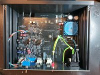
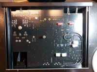
That's nice to hear. My meter doesn't measure down to uV's, but since everything seem to be ok I actually tried it for the first time today. And I must say it sounds better than anything I heard before (both commercial and DIY). So quiet too. Listened to it with a Ortofon Quintet black MC with loading impedance set to 74 ohms and system gain to 0 dB (cartridge output should be about 60uA if I done the math correct).
Thanks for a very kit and your excellent support. This has been a challenging project, and by far the most fun to build.
Attached some pics of my build. The only thing I regret is using the red caps from Wurth instead of Panasonic, couldn't find the right ones at first. Don't like to recap and risk damaging the board just beacues the may fail in the future. So time will tell the quality of Wurth caps I geuss.
Attachments
Nice Build!
Thanks for your kind comments - I appreciate it. I’m very pleased you like it! It will probably settle down and really start to sound good in a week or so. I leave mine on permanently- it only draws about 2 W off the mains.
I think the Wurth caps will be good - German quality!
Thanks for your kind comments - I appreciate it. I’m very pleased you like it! It will probably settle down and really start to sound good in a week or so. I leave mine on permanently- it only draws about 2 W off the mains.
I think the Wurth caps will be good - German quality!
Well you deserve it. Looking forward to se how it performs after some time, leaving it on from now.
But just of curiousity how this offset servo works. Every time it is turned on the offset voltages swings until it settles. This offset currents I assume is far to low to damages the catridge. Haven't measure the voltages with anything coneced to the inputs, and with catridge impedance of 20 ohms or so this will never be a problem, right?
But just of curiousity how this offset servo works. Every time it is turned on the offset voltages swings until it settles. This offset currents I assume is far to low to damages the catridge. Haven't measure the voltages with anything coneced to the inputs, and with catridge impedance of 20 ohms or so this will never be a problem, right?
No it’s not a problem- the current out of the input is limited to about 1mA peak for s few seconds, and in most implementations the worst case initial offset is just 10’s of mV.
Did you measure the voltage at U28 and U29?
Did you measure the voltage at U28 and U29?
No it’s not a problem- the current out of the input is limited to about 1mA peak for s few seconds, and in most implementations the worst case initial offset is just 10’s of mV.
Did you measure the voltage at U28 and U29?
No, but I did now. After input offset voltages stabilized to 0,1 mV (lowest my DMM can show). I measured;
U28 -339mV
U29 -164mV
So what does that tell us? That there is some space left for the serve to make the inputs zero I guess?
Another interesting thing I noticed while playing som records is that the rumble filter seems to to a better job than my previous Pro-Ject preamp with -12db/octave @20hz rumble filter. With this one I could sometimes se some large cone extrusions in the speakers, but not with the X-altra. Just wondering what is the rolloff for the 20hz filter?
Those numbers are 100% correct. 👍 What you are reading there is the servo error correction signal to the bases of the input transistors (this goes via the 330 k resistors). This error correction signal holds the input offset to within +-6 uV typical.
The rumble filter is -40 dB/decade (12 dB/Octave). And you can switch it between 20 Hz and 45 Hz (it might be the Project turnover frequency is different).
The rumble filter is -40 dB/decade (12 dB/Octave). And you can switch it between 20 Hz and 45 Hz (it might be the Project turnover frequency is different).
I could not find the AMVECO3.2VA (part no. 70013K) transformer, I did find a 70023K which is a 5.0 VA. Both are rated for secondary side at 2 X 15 V (full load), the original has a secondary current of 107 mA, the new one has a secondary current of 167 mA.
Where are you located? I have an extra Talema 70013K transformer and am located in the US. PM your address if you'd like me to look into shipping. If you're in the US, it'll be cheap to ship.I could not find the AMVECO3.2VA (part no. 70013K) transformer, I did find a 70023K which is a 5.0 VA. Both are rated for secondary side at 2 X 15 V (full load), the original has a secondary current of 107 mA, the new one has a secondary current of 167 mA.
Decatur, AL 35603. Not sure how to PM or if this is a PM?Where are you located? I have an extra Talema 70013K transformer and am located in the US. PM your address if you'd like me to look into shipping. If you're in the US, it'll be cheap to ship.
- Home
- Source & Line
- Analogue Source
- Bonsai’s X-Altra MC/MM Phono Preamp