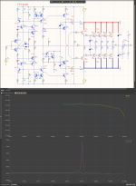
Hmm, the second scheme is interesting - the selection of a trimmer to the third decimal place to set zero in the model, this is serious? in practice, the position of the operating point with such an adjustment, I think, will float ...Here is the result of measuring the spectrum of two amplifiers at the same load with the same output voltage on the 4th period.
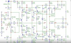
the second question is how linear the amplification (open loop) is in the audio frequency band of the transistor side Q1Q2Q6 at point "A" - noted in the attachment.
Attachments
A great attempt to dump the load on another person, but I did not expect anything else, although I did not declare any achievements in this topic. But I expected you to start entering incomprehensible variables again without explanation.Personally, I see no prospects for this scheme.
Sandi proposed his own current feedback circuit, but it has nothing to do with the original.
judging by the like of the fagos, apparently he knows how to improve it
Pay attention, gentlemen, to the normalized slew rate (NSR), which is attributed to the diagrams. Nothing is said about what it is normalized to. For example, Paul Skritek normalized to one volt of the output signal, for the convenience of using the nomogram in his book in section 3.5.1. However, knowing petr_2009, I assume that he has his own point of view on this aspect.
Pay attention, gentlemen, to the normalized slew rate (NSR), which is attributed to the diagrams. Nothing is said about what it is normalized to. For example, Paul Skritek normalized to one volt of the output signal, for the convenience of using the nomogram in his book in section 3.5.1. However, knowing petr_2009, I assume that he has his own point of view on this aspect.
offtopic:
phagos, if you understood the physical meaning of the normalized slew rate, you wouldn't be asking stupid questions trying to make a fool of others.
Hennady, I hope you understand that the constant voltage at the output can reach 50 mV and even more without significantly affecting the sound quality. In the model, I set zero as accurately as possible using the trimmer, so that the constant voltage does not affect the measurement of distortion by the compensation method. I hope this is clear.Hmm, the second scheme is interesting - the selection of a trimmer to the third decimal place to set zero in the model, this is serious? in practice, the position of the operating point with such an adjustment, I think, will float ...
Attachments
You didn't even bother to write my nickname correctly. I don't expect much from you, because instead of clarifying what you meant, you again allow yourself personal attacks like an offended teenager. If you use any terms, please explain what you mean by them and what physical meaning you mean. Yes, I don't understand the meaning of your normalized rate of rise, since you didn't even specify a normalizing value. There are no notes here, but you pretend that you have told everyone everything and once again allow yourself to look down on yourself, as if you are a carrier of sacred audiophile knowledge, and the rest of the students. Come down from heaven to earth, you do not shine with knowledge, as you invent.phagos, if you understood the physical meaning of the normalized slew rate, you wouldn't be asking stupid questions trying to make a fool of others.
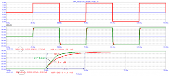
And the maximum rate of rise /fall should be measured in the area with the maximum steep rise / fall, as reflected in the name itself, otherwise it is not the maximum value. You have captured a zone with two different time constants, so in fact your figures do not fully characterize any of them. Don't thank me.
Not convincing. I know for sure that the stability of the operating point with a deviation of no more than 5 millivolts in the established mode really has a positive effect on the quality.Hennady, I hope you understand that the constant voltage at the output can reach 50 mV and even more without significantly affecting the sound quality.
It is not clear the need for a buffer on JFet for simulation, C1 for simulation results is still shorted with a jumper ....
What about the second question?
Hennady, give an example where such measurements are carried out and explain what is the meaning of such a measurement.What about the second question?
Moreover, the point you indicated is not the input of the output stage, there are two such points and their distortions in the push-pull circuit are largely mutually compensated.
offtopic:
fagos, if you want to understand electronics, open textbooks, STANDARTs and study, and do not engage in speculation and flood in a boorish form: I either spin like a flugel, or like a fish in a frying pan, etc. etc.
Same as it ever was....offtopic:
fagos, if you want to understand electronics, open textbooks, STANDARTs and study, and do not engage in speculation and flood in a boorish form: I either spin like a flugel, or like a fish in a frying pan, etc. etc.
Pertr, you have to know that this is DIY, and mostly amateurs here. If you know better you have to have patience and explain things if you know to explain.
Most people here use LTspice and dB, and your diagrams are confusing for most.
Most people here use LTspice and dB, and your diagrams are confusing for most.

Why dodge such a simple question for you? It is not difficult to even write the gain figure at the corresponding frequency, because. You already have the model, why not?give an example where such measurements are carried out and explain what is the meaning of such a measurement.
The meaning of - this is an indirect indicator of the sound quality of a practical model, without delving into the parameters beyond the minimum group delay speed, which, it seems to me, is very far from the actual sound quality of the final amplifier operating on a real load.
here it’s more interesting, because from your words we can conclude that a single-ended JFet is needed to add even harmonics, why?Moreover, the point you indicated is not the input of the output stage, there are two such points and their distortions in the push-pull circuit are largely mutually compensated.
These points are really important, since they are high-resistance and there is a progressive correction in them, depending on the linearity of the assembly, the need for limiting the spectrum at the input will depend, this of course will numerically increase the group delay and will reduce slew rate parameters that you are promoting, however this will be more objective reality, and this will add necessary conditions for practical implementation, while this is only a model ....
Last edited:
Well, petr_2009 can't answer any question in a meaningful way because in his head there is a house of nonsense he read somewhere and he doesn't understand at all.
I already told him that if he wants to see how the amplifier behaves, he should look at its output, the place where the feedback is taken.
But instead in post 181 he compares two amplifiers in a completely incorrect way.
The first is without an RL circuit in the output, and there you can really see the output of the amplifier. And such an amplifier, if you load it with 2uF capacity, it does not become a resonant circuit.
The second amplifier already has such an RL circuit, and above all, the output of the amplifier is not looked at, but the load after the RL circuit, which is not covered by feedback, is looked at.
Why do you think we are idiots and why do you think no one will see this.
And finally read what kind of animal this group delay time is and realize that it is not real signal delay.
And that's why it's incredibly stupid to compensate for the phase shift with a delay line.
Yes, once upon a time, when you and I were young, there was such a method for measuring THD, you subtract from the output signal of the amplifier that of the generator and the difference is THD.
But there people with brains to compensate for the phase shift caused by the amplifier because it is not of infinite bandwidth compensate this with a capacitor in parallel with one of the resistances.
The other method is for the generator to have a 90 degree output
Attachments

Again, instead of answering essentially, you turned to personalities. There's probably nothing to say, so you're nervous. No need to refer me to textbooks, it's better to read it yourself and then maybe it will become clear that if the maximum slew rate is measured, then you need to take the section with the maximum derivative. This has already been discussed at a Russian-language forum, including with your participation, but you did not take anything out of this discussion, but persistently consider yourself the smartest. Remind me where you were wrong and I had to point a finger at you, or will you change your tone and communicate like a normal person?fagos, if you want to understand electronics, open textbooks, STANDARTs and study, and do not engage in speculation and flood in a boorish form: I either spin like a flugel, or like a fish in a frying pan, etc. etc.
Any amplifier can be made to be stable at a 2uF load by changing the trim (R22/C4)
But of course this will raise the THD.
The method of decoupling the capacitive load from the reverse LR circuit circuit is preferred.
The wheel was invented a long time ago, but not for everyone.
Of course, this slight rise at 576KHz can be removed, but it is foolish to further degrade the THD.
You advise people to read, why don't you take advantage of this advice.
I am uploading some literature on the matter.
And even how to make an amplifier with a negative group delay time
That is, the signal at the output appears before it is applied to the input.
If your personal theory was correct that the group delay time is the time it takes the signal to reach the output.
Attachments
Sandy, this example with negative GD has already been discussed somewhere and I explained how it works. In the negative group delay example, I showed that two zones (before and after resonance) have lead the signal envelope. But in one case, the burst components themselves are delayed, and in the other case, it has a lead, as in a RC-chain in a steady state.
Better tell what do you understand by the physical meaning of the “time Propagation Delay” parameter? This is much closer to audio frequency amplifiers.
https://www.diyaudio.com/community/...amental-improvement-sandy.346751/post-7140842
Better tell what do you understand by the physical meaning of the “time Propagation Delay” parameter? This is much closer to audio frequency amplifiers.
https://www.diyaudio.com/community/...amental-improvement-sandy.346751/post-7140842
Last edited:
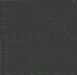
I don't understand what it will give youthe second question is how linear the amplification (open loop) is in the audio frequency band of the transistor side Q1Q2Q6 at point "A" - noted in the attachment.
Attachments
actually a lot...I don't understand what it will give you
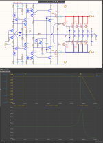
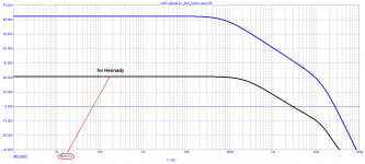
the picture is beautiful, but the only question is the unity gain frequency (blue open loop gain graph), 27 MHz for laterals? seriously?
there are practical implementations of such a miracle of modeling?
P.S. I look at the graphs of the results of your simulation in post #181. Do you really think that the results you show are relevant to practical implementation? I will feel sorry for the radio amateur who undertakes to implement this, in fact, "raw" scheme ...
Last edited:
It is precisely this misconception (tDT) and feedback that I have had many arguments with electronics engineers.
They even have a hard time understanding this matter.
Maybe it's the other way around, it's you who don't understand this issue. Over a year ago, I recommended that you study Dostal's book. You will not find a more sensible description of all types of distortions anywhere.
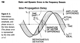
Here is a picture explaining the types of distortions.
Attachments
Hennady, are you involved in the design of amplifiers? The question arose because you are talking about the performance of the amplifier according to the signs by which the developers not judge.actually a lot...
the picture is beautiful, but the only question is the unity gain frequency (blue open loop gain graph), 27 MHz for laterals? seriously?
there are practical implementations of such a miracle of modeling?
P.S. I look at the graphs of the results of your simulation in post #181. Do you really think that the results you show are relevant to practical implementation? I will feel sorry for the radio amateur who undertakes to implement this, in fact, "raw" scheme ...
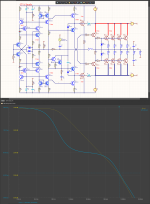
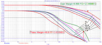
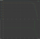
Here is a graph of the loop gain with additional reactive load. What does this chart tell you?
Attachments
A non-feedback amplifier.
10Hz "delay" 233uS
100MHz "latencies" 11nS
Either it's a physical miracle, or it's not time for the signal to pass through the amplifier.
If the wires in the amplifier between the input and the output are 1 meter long, then the output signal will be delayed by 3.3nS and during this time the feedback will not work.
But it's rarely even 0.1m, so we roughly say 330pS.
We introduce feedback that should, in your opinion, 233uS not work.
And a new miracle, not only the robots, but also the delay time of the group became 10,000 times less.
Through the same slow amplifier, the same signal went 10,000 times faster.
There must be something rotten in Denmark or in someone's head.
You only have to look at the definition of group delay time to see that it is not the time for the signal to pass through the amplifier. it is simply a relationship between phase shift and frequency shift..
It's good that you read Dostal's book, it's a pity that you didn't understand anything.
It is a vector error. It is the sum of two errors, amplitude and phase.
Yes, I solved such a problem 40 years ago when I was developing complex measuring equipment.
There, in order for the phase error of a signal with a frequency of 50HZ to be small, I had to use the NE5534 amplifier because of the 15MHz frequency band.
But these things have nothing to do when it comes to audio.
I am not an amateur and electronics is not a hobby for me but a profession.
And audio is the simplest part of electronics.
Attachments
- Home
- Amplifiers
- Solid State
- Apex A40 fundamental improvement. (Sandy)