I am planning to do exactly that (dye and PVA).I like it. You can use liquid leather dye to color those panels. I used black for mine and applied over my PVA/water coating and seemed to work just fine. Two coats crisscrossed. How many watts are those exciters? Two are way overkill for EXP panels that size in my testing (24w), but I see you got your 8ohm by using 2 so never mind.
Dear DML builders, I would like to suggest you to have a look to Andre's work in the thread "DML PA systems" Leob has opened for PA applications. Start for example at 58.

Does anyone have experience with the "DAEX58FP Flat Pack 58mm Exciter 25W 8 Ohm." I need to make a call on buying a couple of these. I plan on using epoxy on the base to flatten them out as the leads make the face plate uneven. I also don't plan on bolting them to the panels but rather use them as you would traditional exciters. thanks
Yep, I plan on mixing the dye right in with the PVA/water next time as it is a water based dye.I am planning to do exactly that (dye and PVA).
https://www.amazon.com.mx/gp/product/B08P4465LQ/ref=ppx_yo_dt_b_asin_title_o09_s00?ie=UTF8&th=1
I don't but the hf seems limited and I wonder if it's because of the large mounting plate...Does anyone have experience with the "DAEX58FP Flat Pack 58mm Exciter 25W 8 Ohm." I need to make a call on buying a couple of these. I plan on using epoxy on the base to flatten them out as the leads make the face plate uneven. I also don't plan on bolting them to the panels but rather use them as you would traditional exciters. thanks
The Bl value is good though, so plenty of punch it seems.
If you do buy them, if you can, I'd locally groove the panel slightly rather than put a thick epoxy bed on it to overcome the lead bumps.
The large plate is my concern...
Cheers
Eucy
Yes I have a pair. See https://www.diyaudio.com/community/...s-as-a-full-range-speaker.272576/post-7094797Does anyone have experience with the "DAEX58FP Flat Pack 58mm Exciter 25W 8 Ohm." I need to make a call on buying a couple of these. I plan on using epoxy on the base to flatten them out as the leads make the face plate uneven. I also don't plan on bolting them to the panels but rather use them as you would traditional exciters. thanks
This model is a faulty design I will say. The square back plastic too soft and not flat. When you screw it to a panel, the center of the square will not contact the panel tight. There is a gap in between and cause hammering noise on high volume. If you glue instead of screw may have different result.
I spend a whole afternoon to remove the square back. It's a nightmare...... because after you remove it. You will lost both +/- wires from the voice coil. I have to make an operation on the voice coil to seed out the wires end. It's just 2mm long and hair size thin. Then resolder them to the extension wire.
DON'T buy it!
Go buy the PUI ASX05408-HD-R (or 04 if you want 4ohm). It has the exact same driver as the DAEX58FP.
Try it on a ceiling tile could make for an interesting set up for a conference room.Edit oct 27, 2021: a nice Google drive library of DML publications by vdljev:
DML - Google Drive
Edit April 1, 2020: nice summary of DML patents by Burntcoil
A Study of DML's as a Full Range Speaker
Edit Aug 12, 2019: Nice summary here by BurntCoil on how to maximize performance.
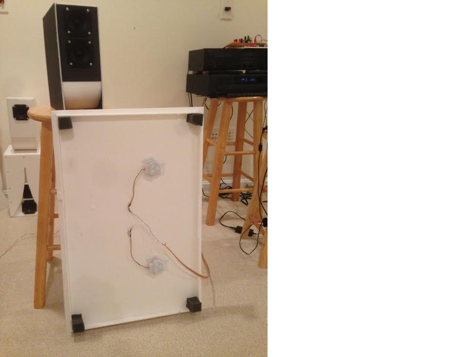
I had some cheap exciters that I got from PE a while back and tested them out a while ago with a full 20x30in FC panel here:
Foam Core Board Speaker Enclosures? - Page 225 - diyAudio
I found that a large 20in x 30in panel can sound quite good with nice bass extension and a snappy transient response:
Impedance:
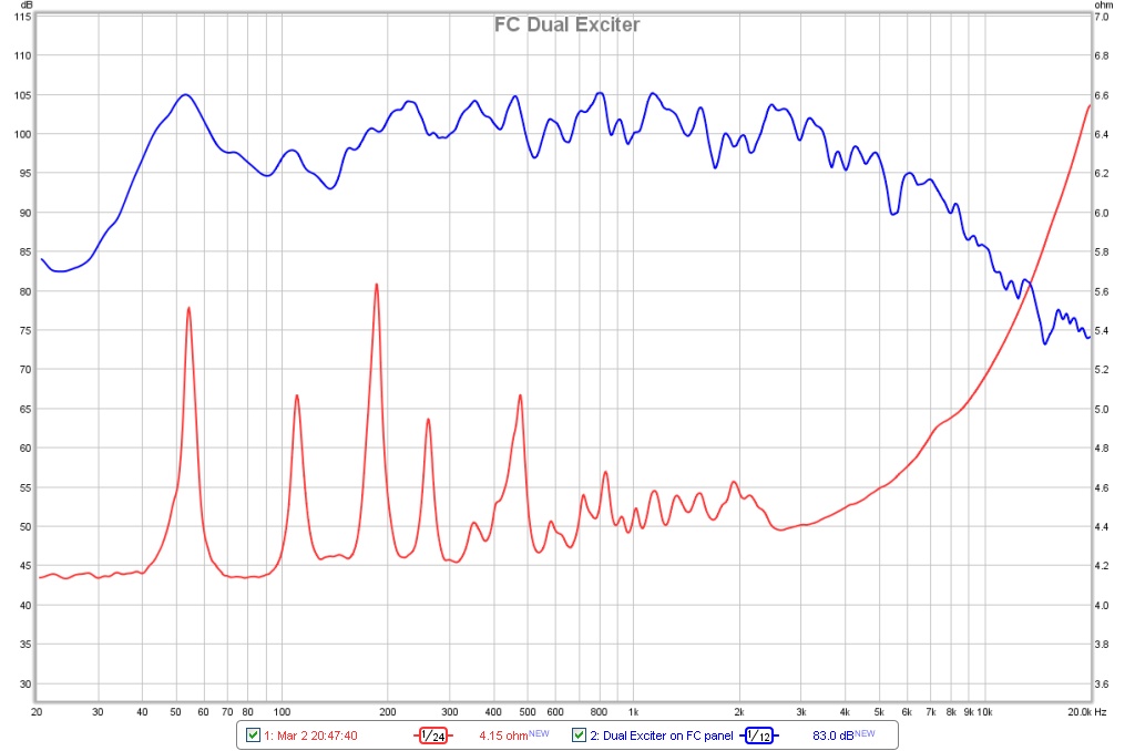
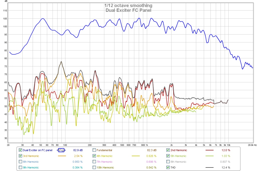
Frequency Response & Harmonic Distortion:
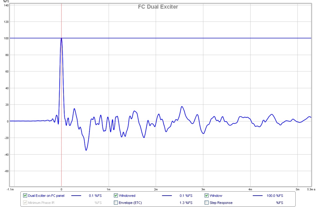
Impulse Response:
The results were interesting in that it sounded nice - with surprising bass and good midrange. I thought nothing more about it until recently prodded by the master of DML, CLS. He has worked on this extensively and is a treasure trove of good info. I since have discovered that you can really do some cool things with them by playing with driver placement, cutouts, adding mass, adding felt, adding ribs, making them huge, making them multi-way FAST, etc. the options seemed almost limitless. Take for example, a large center channel and a super 40Hz capable multiway that CLS built here: PIEZO NXT type panel - Page 60 - diyAudio and PIEZO NXT type panel - Page 61 - diyAudio
I feel like this technology just isn't getting enough attention. There are several very large threads on this on the web. It might be tough for a newbie to comb through. I am a newbie at this so thought I would document my journey for the Full Range forum to follow. I think it really could be a great full range speaker with some careful experiments. This will be really useful with some modeling using CAD and FEA modal analysis - such as available in many CAD packages like SolidWorks. One can play with shapes, cutouts, mass loading, variation in thickness and materials, boundary clamping conditions, etc. The idea is to spread the modes evenly with not any one mode dominating and causing a spike.
First thing is to play with it to get a feel of what we are dealing with. What is nice is that it is relatively cheap to play with. Exciters cost $3 to $20 ea and can be made by removing or cutting out large holes in the cone from an old driver and leaving the spider and VC to attach to the panel. Foam core or corrugated cardboard doped with shellac or PVA seems to be the materials of choice.
Some interesting facts:
1. Although it has no baffle, it is not an open baffle (OB) dipole in behavior - that is, there is no huge bass rolloff and it hits surprisingly low (40 to 50Hz is easy) for a zero baffle driver.
2. It is not a dipole but behaves more like a bipole or an omni.
3. It has very quick snappy transient response - nice drum sounds.
4. It is sensitive to how you mount it or frame it or hold it.
5. You are building a driver in reality - a driver and zero enclosure.
6. You want to avoid symmetric shapes and symmetric exciter placement in order to reduce the effects of the main symmetric transverse drum head eignmodes. Think reflection anti-symmetric shapes like uneven trapezoids, pentagons, blobs, etc.
7. It operates more by having high velocities and large areas for good efficiency vs large displacements - thus small drivers and large panels can be surprisingly loud.
8. The impedance is essentially "flat" relative to normal drivers in that there are modal peaks (many of them) but they range from nominal Re value (say 6 ohms to maybe 8 or 9 ohms throughout the 40Hz to 20kHz range - this presents a very flat load to an amplifier.
Here is a photo of a basic panel I was testing (right before I cut off some edges to form a trapezoid) - panels is about 1 square ft in size and made of standard dollar store foam core board. I suspended it with two pieces of twine from the top corners between a ladder to reduce the effects of edge boundary clamping:
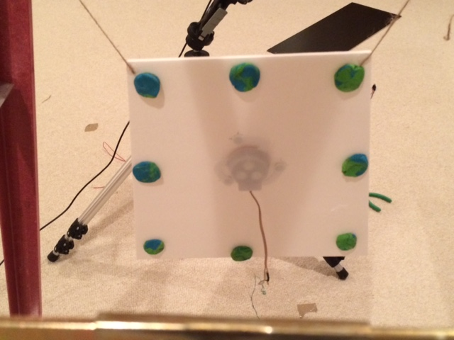
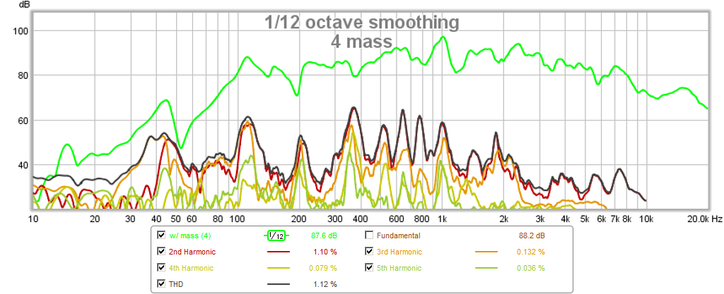
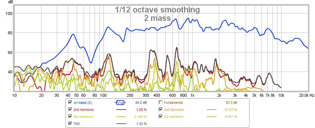
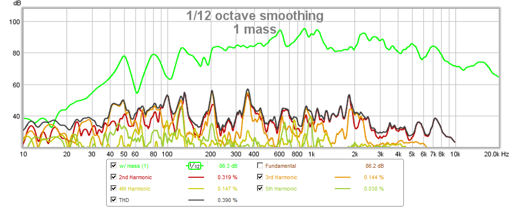
Then I started to play with mass loading by adding blobs of modeling clay (8, 5, 4, 2, 1, 0) so you can see the effect on the resonance modes and the harmonic distortion. What is neat with this test is you can do it live while playing music and immediately hear what sounds more pleasing to the ear. Note the 50Hz bass extension. It is also surprisingly efficient with 85dB and a puny little voice coil. These are 0.5m and 0.71v for equivalent SPL at 2.83v and 1m.
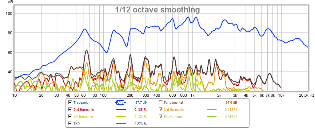
Frequency Response and Harmonic Distortion for...
No added mass:
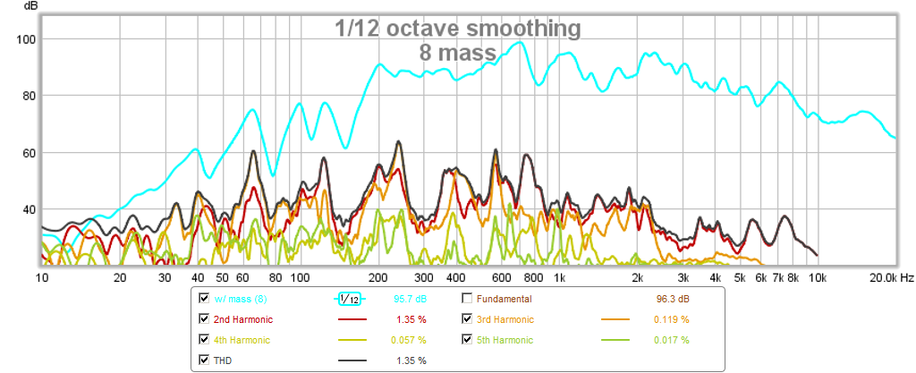
8 pieces of added mass:
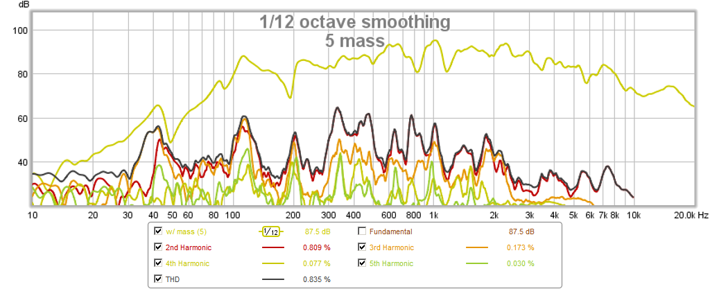
5 pieces of added mass:
4 pieces of added mass:
2 pieces of added mass:
1 piece of added mass:
Impulse Response of 1 piece of added mass, note the sharp transient capability with relatively low after pulse or ringing:
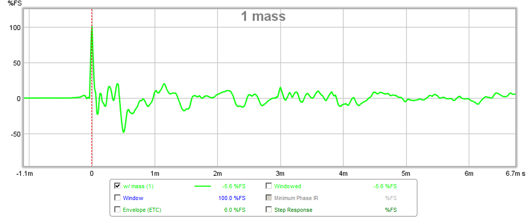
I liked the sound of the 5 and 1 mass the best and for a FAST with a 200Hz XO, the 5 mass might actually do fairly well. Of course, sound clips to follow once I have more time to work on this. Just to demonstrate how quick and easy this is, I did all these experiments in less than an hour including making the DML.
Thanks, good idea on the groove.I don't but the hf seems limited and I wonder if it's because of the large mounting plate...
The Bl value is good though, so plenty of punch it seems.
If you do buy them, if you can, I'd locally groove the panel slightly rather than put a thick epoxy bed on it to overcome the lead bumps.
The large plate is my concern...
Cheers
Eucy
Thank you. I was hoping someone had experience removing the plate or at least cutting it down to a small circle. Good to know the plastic is soft....not good. I'll research more exciters including your suggestion because I really need 8 Ohm for this project.Yes I have a pair. See https://www.diyaudio.com/community/...s-as-a-full-range-speaker.272576/post-7094797
This model is a faulty design I will say. The square back plastic too soft and not flat. When you screw it to a panel, the center of the square will not contact the panel tight. There is a gap in between and cause hammering noise on high volume. If you glue instead of screw may have different result.
I spend a whole afternoon to remove the square back. It's a nightmare...... because after you remove it. You will lost both +/- wires from the voice coil. I have to make an operation on the voice coil to seed out the wires end. It's just 2mm long and hair size thin. Then resolder them to the extension wire.
DON'T buy it!
Go buy the PUI ASX05408-HD-R (or 04 if you want 4ohm). It has the exact same driver as the DAEX58FP.
So I decided to go with a pair of
Also, does anyone know what they mean about "steered flux" or is it just marketing? I see they charge a premium for those. thanks
DAEX32Q-8 Dual Steel Spring Balanced 32mm
I'm going to lose 5w but they are 32mm instead of 58mm which I think would be better in the highs. They come with the new "quick release" attachment for experimenting, but without several "base" pieces to attach to several panels, I don't see the diff.Also, does anyone know what they mean about "steered flux" or is it just marketing? I see they charge a premium for those. thanks
Steered flux patentSo I decided to go with a pair of
DAEX32Q-8 Dual Steel Spring Balanced 32mm
I'm going to lose 5w but they are 32mm instead of 58mm which I think would be better in the highs. They come with the new "quick release" attachment for experimenting, but without several "base" pieces to attach to several panels, I don't see the diff.
Also, does anyone know what they mean about "steered flux" or is it just marketing? I see they charge a premium for those. thanks
https://patents.google.com/patent/US20140265709A1/en
Eucy
I don't quite understand that patent. But it does seem as-if 'steered flux' can only be applied to a multiple coil assembly. Does the Dayton 'steered flux' driver have multiple coils in it? (Some subs woofers do, but... space limitations in an exciter...?)
If not, then it seems that it's just marketing gumpf and a neodymium magnet assembly would explain the high efficiencies.
https://www.daytonaudio.com/product...eable-hardware-mounting-mounting-plate-5-packbut without several "base" pieces to attach to several panels, I don't see the diff.
Hello AndreHave any of you tried to measure the T/S parameters of an exciter mounted onto a panel?
Not from my side because there is nothing for me behind (or I haven't understood it...). With a standard pistonic loudspeaker, it opens to load design, for DML?
What is in my do list (and stays for now in my do list...) is to get some impedance curve. 2 things to read in it : the frequencies of resonance in relation to the FR and probably more interesting but not sure it is possible to extract it, the part of the impedance due to the mechanical impedance of the panel. This second information is probably hidden by the inductance of the voice coil.
You can get T/S from the Fs only. But you need two Fs impedance curves: with the speaker under test either mounted into two different sealed-box volumes; OR, you can get T/S parameters from two different Fs frequencies by using different weights added onto the drivers. I'm going to try this with drivers mounted onto panels and mess around with weights and see if I get anything useful.Hello Andre
Not from my side because there is nothing for me behind (or I haven't understood it...). With a standard pistonic loudspeaker, it opens to load design, for DML?
What is in my do list (and stays for now in my do list...) is to get some impedance curve. 2 things to read in it : the frequencies of resonance in relation to the FR and probably more interesting but not sure it is possible to extract it, the part of the impedance due to the mechanical impedance of the panel. This second information is probably hidden by the inductance of the voice coil.
I would love to see this explained in a speaker application, as in an exciter cut down the center and someone explaining every little aspect of it from construction to what exactly happens with the flux when power is applied.I don't quite understand that patent. But it does seem as-if 'steered flux' can only be applied to a multiple coil assembly. Does the Dayton 'steered flux' driver have multiple coils in it? (Some subs woofers do, but... space limitations in an exciter...?)
If not, then it seems that it's just marketing gumpf and a neodymium magnet assembly would explain the high efficiencies.
The patent is for motors that can replace copper wound style motors, doing away with the copper bindings all together.
"The rotor in the present invention merely switches, or steers, flux from one place to another rather than being the source of a rotating magnetic field."
I cant make out the exact patent process but they have backward angled "teeth" that the flux fills in to cause friction sufficient for movement? They use a unipolar steered flux which I'm still gonna' try to research more and see what's up.
I'm also going to try and ask about this over at Parts Express and see if I get some kind of reply. I don't mind spending the extra money if they would explain the extra benefits and longevity to a fuller extent. The actual fabrication may be a trade secret but I sure do want to know more.
Last edited:
I saw that , thanks. $10 for 5
I also want to see if the HF booster disc has an Fs of its own...Hello Andre
Not from my side because there is nothing for me behind (or I haven't understood it...). With a standard pistonic loudspeaker, it opens to load design, for DML?
What is in my do list (and stays for now in my do list...) is to get some impedance curve. 2 things to read in it : the frequencies of resonance in relation to the FR and probably more interesting but not sure it is possible to extract it, the part of the impedance due to the mechanical impedance of the panel. This second information is probably hidden by the inductance of the voice coil.
I used those methods and it works well for pistonic speaker. It is based on 2nd order model of those mass driven drivers. DML are not mass driven so I have doubts... In an other hand, experimenting is always useful. Something else might goes out your observations.You can get T/S from the Fs only. But you need two Fs impedance curves: with the speaker under test either mounted into two different sealed-box volumes; OR, you can get T/S parameters from two different Fs frequencies by using different weights added onto the drivers. I'm going to try this with drivers mounted onto panels and mess around with weights and see if I get anything useful.
To have a look to the impedance vs frequency is a good idea.
- Home
- Loudspeakers
- Full Range
- A Study of DMLs as a Full Range Speaker