I agree - but I have little hope that you will be more successful than all the other members here who have give up to discuss with that man. It is obvious that he never responds to any questions but perpetually repeats his statements like a religious fanatic.I don't take it as an argument.
The man is clearly not a specialist in the field of electronics, I have been engaged in design work in this field for more than 50 years.
And with far more complex things than audio amplifiers.
I'm just struggling to explain otherwise basic things to him, hoping he'll still understand something.
It is precisely this misconception (tDT) and feedback that I have had many arguments with electronics engineers.
They even have a hard time understanding this matter.
Well, audio has always been primarily a religious sect, where faith has long defeated common sense. 😉
You are right, these (and many other OPAs) were apparently developed by sectarians from audio loversWell, audio has always been primarily a religious sect, where faith has long defeated common sense. 😉
Attachments

Well, you're just showing that you don't understand anything about amplifiers and which parameter means what.
This is no time for a group delay.
When an amplifier is fed a rectangular pulse with a higher speed than its own, it naturally overloads for a certain time. And he needs time to get out of this overload.
But no amplifier in audio works in such modes.
Here's an example of a group delay time:
An amplifier with gain 10000 Ft=1.59MHz, first pole 159Hz has 1mS (tTD) as you write it although it is not true.
by giving it feedback with a depth of 10 and making it gain 1000x now tDT becomes 100uS
At a gain of 100 tDT = 10uS
At gain 10 tDT = 1uS
And the amplifier is practically the same.
A 1MHz bandwidth amplifier has 159nS group delay.
Same as RC group with 1MHz cutoff frequency.
And it does the same fancy "Speed Distortion" as an RC group.
A 10MHz bandwidth amplifier has 15.9nS group delay.
A 100MHz bandwidth amplifier has 1.59nS group delay.
We already had this argument with you in Telegram, but apparently you will never understand anything.
Hopefully this argument here is helpful to someone else who is delusional but has a chance to understand what is going on.
Last edited:

Just as a car cannot immediately start from a standstill at a speed of 100kM/h, the output of an amplifier cannot immediately start at a certain speed.
It takes time to get up to speed.
The exit is not as late as you think.
It starts immediately with the input impact, but needs time to accelerate as much as the input.
And this is not a delay in the physical sense.
Time to speed up!!!!
And by measuring the bandwidth of the amplifier we immediately know how accurate this acceleration time is.
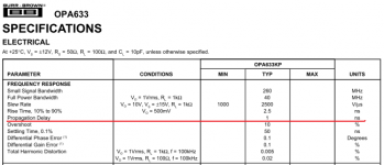
Sandy, the time Propagation Delay is a dynamic parameter, the same as Slew Rate and Rise Time, and characterizes the ability of the amplifier to quickly respond to voltage changes such as amplitude and frequency.
At one time, I gave you this fragment from Jiri Dostal's book for study, but you still did not understand anything.
Well, since you gave an analogy to electrical processes in the mechanics of cars, let's imagine such a situation. There are two cars that have to go a distance with winding sections of the road where there are flags on the turns (as for a skier descending from the mountains). But one car has new tires, and the other is worn (bald).
A car with a new tire turns exactly, does not knock down the flags, and in which the worn rubber constantly knocks down the flags, and the steeper the turn, the more it knocks down the flags.
The question is: which car will pass the distance more accurately without knocking down a single flag on the turns?
When you answer this question for yourself, you will probably understand what high-speed distortion is and how it affects the quality of sound amplification.
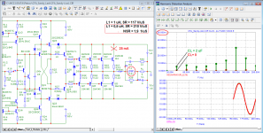
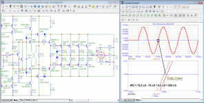
I tried to figure out why the Hafler XL-280 amplifier passes its SWDT test, and the sound quality does not meet the requirements for reference amplifiers.
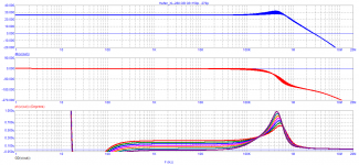
To do this, I typed a model of this amplifier and took a Bode diagram with various values of the trimmer capacitor C6.
As can be seen from the diagram, in the audio range, the group delay can be set up to a negative value. For example, for a frequency of 20 kHz, according to the formulas from Jiri Dostal's book, the group delay should not exceed 8 ns, which is easy to do.
But why then the amplifier does not sound as it was intended by the author? The answer is simple. The author tested on a sinusoidal signal of constant amplitude, i.e. in steady state.
If we carefully look at the group delay graph, we will see that the group delay persists only in the audio range, while immediately after the audio band, the group delay level begins to rise, which reaches 600 ns at a frequency of 300 kHz!
I hope there is no need to explain that when both the frequency of the signal and its amplitude change (which constantly takes place in audio signals), the spectrum of the signal changes, it is enriched with higher harmonics, which are also important to amplify with high accuracy both in amplitude and in phase.
Therefore, the conclusion suggests itself that in order for the amplifier to amplify the signal as accurately as possible, it is important not only the group delay that meets the SWDT requirement, but also its constancy up to at least 300 kHz! (preferably higher)
Attachments
what kind of amplifier with such group delay parameters?If we carefully look at the group delay graph, we will see that the group delay persists only in the audio range, while immediately after the audio band, the group delay level begins to rise, which reaches 600 ns at a frequency of 300 kHz!
Somehow, in terms of topology, this will probably be due to the frequency dependence of the input impedance of the driver stage - and why such an amplifier will sound good? it's not real...
petr_2009, a hump on the high-frequency part of the Bode diagram of a closed-loop amplifier indicates poor stability. What else do you want to find in an amplifier that is not even stable? There are two options here - either the amplifier was really poorly made, or your model does not correspond to reality. But there is no need to talk about any search for invisible entities that spoil the sound from such a situation.
By the way, have you heard HaflerXL-280? Does it really sound bad or are you guessing from the reviews of others?
By the way, have you heard HaflerXL-280? Does it really sound bad or are you guessing from the reviews of others?
probably the process of modeling and analysis of the results is not yet completely finished.or just simulated measurements?
even a practical option will only be a trial option. Many find it very difficult to analyze the opponent's critical thinking.
ok, if the author of the modification does not need it, then it will be possible to take ideas for further improvement for the next creation...
Amplifiers with current feedback are very fast, but for some reason they are rarely classified as comfortable sounding. This needs to be dealt with, and the THD coefficient is not entirely objective to the quality of the subjective perception of sound.
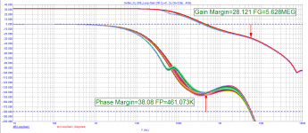
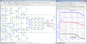
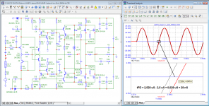
Amplifier stability is judged from the loop gain diagram, not speculation from the Bode diagram. Here is a diagram of the loop gain in all group delay tuning modes with a capacitive load from zero to 2 uFpetr_2009, a hump on the high-frequency part of the Bode diagram of a closed-loop amplifier indicates poor stability. What else do you want to find in an amplifier that is not even stable? There are two options here - either the amplifier was really poorly made, or your model does not correspond to reality. But there is no need to talk about any search for invisible entities that spoil the sound from such a situation.
Attachments
petr_2009, the Bode diagram of a closed-loop amplifier in an unstable state also has a hump in the RF region. It is one thing when this hump arises due to the interaction of the output filter with the load, and quite another if this hump characterizes the amplifier itself at the output point where the feedback is taken. These are two different cases. Since you did not show the Hafler XL-280 simulation scheme and did not attach the model for verification, there were reasonable doubts.
I'm sorry, but they don't take your word for it here.
I'm sorry, but they don't take your word for it here.
who does not understand, let him not believe. As proof, I gave the Bode diagram with regulators of both the reactive load and the group delay using a trimmer capacitor. What more evidence is needed. The amplifier was mass-produced and had no problems with stability.I'm sorry, but they don't take your word for it here.
Personally, I see no prospects for this scheme.Petr2009, draw your A40 modification, as you think it is correct and ideal
Sandi proposed his own current feedback circuit, but it has nothing to do with the original.
judging by the like of the fagos, apparently he knows how to improve it
https://www.diyaudio.com/forums/sol...-interview-negative-feedback-post1167639.html
Graham
and that is why I have told everyone who is unhappy about suddenly starting sines on my simulated traces to ignore my first cycle energisation. Most audio responses become steady after one cycle, so why is everyone fighting me ?
https://www.diyaudio.com/forums/sol...-interview-negative-feedback-post1197323.html
Those who believe they understand SS NFB amplifiers need to ask themselves why it is that even though all the 'nodes and zeros etc. etc.' are theoretically correct, so often the reproduction still does not sound right !!!!!
Graham raised the issues about 20 years ago, but the "theorists" were stocking up on popcorn to start laughing in the morning.
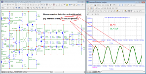
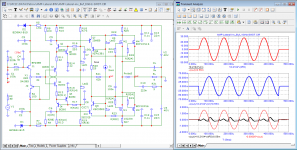
Here is the result of measuring the spectrum of two amplifiers at the same load with the same output voltage on the 4th period.
I hope it is clear that if you measure the spectra in the first period (as Graham did), the difference will be even greater. But in this version of the program, the minimum number of periods is limited to four.
p.s. In fact, the amplifier proposed by Sandy is much better than many other developments (if you do not take into account the shortcomings mentioned above).
Graham
and that is why I have told everyone who is unhappy about suddenly starting sines on my simulated traces to ignore my first cycle energisation. Most audio responses become steady after one cycle, so why is everyone fighting me ?
https://www.diyaudio.com/forums/sol...-interview-negative-feedback-post1197323.html
Those who believe they understand SS NFB amplifiers need to ask themselves why it is that even though all the 'nodes and zeros etc. etc.' are theoretically correct, so often the reproduction still does not sound right !!!!!
Graham raised the issues about 20 years ago, but the "theorists" were stocking up on popcorn to start laughing in the morning.
Here is the result of measuring the spectrum of two amplifiers at the same load with the same output voltage on the 4th period.
I hope it is clear that if you measure the spectra in the first period (as Graham did), the difference will be even greater. But in this version of the program, the minimum number of periods is limited to four.
p.s. In fact, the amplifier proposed by Sandy is much better than many other developments (if you do not take into account the shortcomings mentioned above).
Attachments
Yes, Sandy, we argued. But you didn't understand then, and you don't understand now. Here are the test graphs of your amplifier, study. As you can see, while the phase is constant, constant and group delay.We already had this argument with you in Telegram, but apparently you will never understand anything.
Hopefully this argument here is helpful to someone else who is delusional but has a chance to understand what is going on.
Attachments

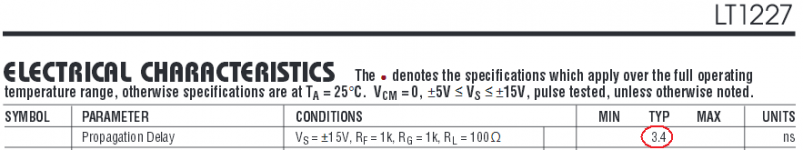
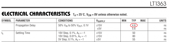
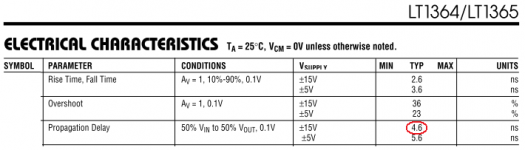
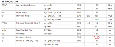
Sandy, to draw a line (so that you finally understand what time Propagation Delay is), I will give the same tests of another amplifier.
When measuring distortion by the compensation method, an ideal delay line of 28 ns was used
When measuring distortion by the compensation method, an ideal delay line of 28 ns was used
Attachments

- Home
- Amplifiers
- Solid State
- Apex A40 fundamental improvement. (Sandy)