All discrete dacs do not using I2S input format.Youve got the best I2S delivery. Great. Thanks for swapping them around. All three I2S boards may sound different, regardless of jitter specs.
Ususaly it is Left justified format. But that is usually not written.
It is 1 BCK cycle LRWS (LE) delayed.
You need just a simple additional logic circuit for that...
It is beeter but if You can find 0.05% go for it.0.1% resistors are fitted.
PPM figure is important too.

if You can find 0.05% go for it.
Do you have any suggestions for other R2R discrete boards with better resistors? I couldn't find any. Soekris is out of stock and besides @batteryman may be wanting a board simpler design with no FPGA.
I hope to test mine next week.Do you have any suggestions for other R2R discrete boards with better resistors? I couldn't find any. Soekris is out of stock and besides @batteryman may be wanting a board simpler design with no FPGA.
I have a CD test disc so I can look at & post the spectra with my Picoscope (compared with the cd player's audio output (TDA1305 CC dac) and the Dacmagic's WM7840s)
post the spectra with my Picoscope
Thats very kind of you. Thanks!
Im just as interested to find out what your listening reveals. With your other multibit DACs you have some great comparators. I guess the AD1862 as a 20bit R2R might be a good match? I haven't seen a balanced AD1862 DAC.
The balanced dac AD1862 is my own design fed from an iancanada I2S to PCM board & DIR9001 spdif receiver. (I haven't yet assembled it)Thats very kind of you. Thanks!
Im just as interested to find out what your listening reveals. With your other multibit DACs you have some great comparators. I guess the AD1862 as a 20bit R2R might be a good match? I hvaent seen a balanced AD1862 DAC. Is it a Wadia?
(Chips are from Rochester via a group buy on here a few years ago)
- Up to 24 bits are converted. At 16 bits the last 8 are zero, they do not work and are irrelevant.
So this is a 16 bit DAC.. I don't fully understand this statement (other than the resistances become difficult so they're left blank).
The balanced dac AD1862 is my own design fed from an iancanada I2S to PCM
Wow. Id like to hear that.
The AD1862N chips measures well for an R2R on the datasheet anyway. Even the standard grade has at worst TOTAL HARMONIC DISTORTION + NOISE @ 0 dB, 990.5 Hz max –92dB (0.0025%)
Thats a pretty hard act for any discrete R2R to follow. eg 0.01% resistors board had THD about -86dB
So this is a 16 bit DAC.. I don't fully understand this statement (other than the resistances become difficult so they're left blank).
The ebay description or the online translation from Italian might be confusing. My take is:
Its a 24bit R2R ladder. That also matches the resistors in the ladder. It accepts 24 bit I2S
It will still accept and process just 16bit data eg if you send CD 16/44.1 over I2S the 8 LSB are just padded.
I hope thats not misleading. I don't have the board.
That's not what he wrote. He meant that if 16bits are input, the last 8 are zero, so if 24 are input, 24 are converted.So this is a 16 bit DAC.. I don't fully understand this statement (other than the resistances become difficult so they're left blank).
AD and other DAC chips are NOT R2R ladder dacs
R2R ladder means that real resistors connected in specific network
against the R2R (without ladder) means that "R" components are emulated with curent sources/sinks
Because of very hard to implement "R" component into the DIE of IC.
.
So these are two different things and should not be compared with neasurements datas directly like the "identical" or the same.
AD and other DAC chips are NOT R2R ladder dacs
AD has published a block diagram of the internals of AD1862 and you can see from here that it contains a 17bit R2R section : https://www.diyaudio.com/community/...st-tht-i2s-input-nos-r-2r.354078/post-7052401
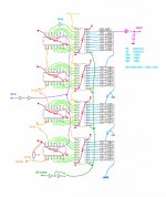
I build this one for 32bit word just to test. It was 4 modules for stereo balanced version. Also tried paralled SE.Do you have any suggestions for other R2R discrete boards with better resistors? I couldn't find any. Soekris is out of stock and besides @batteryman may be wanting a board simpler design with no FPGA.
Working good but maybe 24 bits are enough. Probably digital noise will be smaller.
Value of resistors are not fixed. Someone said the 1mA from "1" that is 5V to 0V is ok that means 5K...
2R value is "last" "R*" so if You are cutting out for the 24 or 16 bits last R in ladder is 2R value
.
I left R2R ladder removable to try with smaller tolerance resistors. (I never had time to try that 🙁 )
So I tested with 1% Rs, The distortion @-60db digitaly attenuated is present and You can even har it in the headphones expecialy. MSB trimm and even MSB-1 trimm are welcome BUT it not solve the problem.
.
So there is a must to use at least 0.1% or even better 0.05% R
.
Dac input format is Left Justified
So please take a look at PMD100 datasheet to find I2S / LJ simple circuit. . I use that before this DAC with Amanero USB/I2S interface. Or use double FlipFlop in series, but without inverted BCK that will "delay" LE for one BCK...
.
DAC is R2R voltage output type. Output resistance are R. This is from merit for optional analog output fiter.
DAC is easely capable to 384KHz SR probably more, very fast reaction for SR change without clicking.
I build it on the test board point-to-point without classc PCB.
.
If You use single 8X 574 logic IC for each bit You can acheive 8X smaller tollerance of used R.
Attachments

Last edited:
Yes But I think that it is not "real" Resistor elements?AD has published a block diagram of the internals of AD1862 and you can see from here that it contains a 17bit R2R section : https://www.diyaudio.com/community/...st-tht-i2s-input-nos-r-2r.354078/post-7052401
The first 3 MSBs are even not in the R2R scheme but encoded to the tjemomether code to 7 bits which going to only "R". Just like in diskrete DSD.
For exact information is there passive R component present in the chip we have to take a look at the magnified DIE iside?
That 16/44 jitter test result does not look that bad as it is 16-bits so sidebands should be visible above -140dB.
Archimago himself wrote this:
"Looking at all those sidebands in the jitter plot, I'd estimate it to be >5ns; but yet it still sounds quite good! IMO, more evidence to say there's no point to quibble about the odd sidebands and whatever picosecond jitter found in well engineered gear..."
I never quite understood the hype surrounding jitter. Like anything, if it is REALLY bad there will be issues. But let's think about what jitter does to the output for a second. Jitter is essentially playback timing errors. Each sample contains the value that the signal is supposed to hold at some exact time. When the playback timing is wrong, the sample's value is produced at a slightly different time. This will change/distort the waveform. But that should be able to be captured in a distortion measurement. If not, then where is the problem manifesting itself?
Jitter can manifest in an FFT as noise, or as skirts around the base of spectral lines. It doesn't necessarily stay steady long enough to show up as steady-state distortion on an FFT. In other words, it can be too time-variant to look like steady-state distortion. What it does to sound can vary depending the particulars of the jitter. I've seen it sound like distortion. Seen it blur stereo imaging. Depends. If a dac is otherwise clean enough, small jitter can be audible. Just hard to describe the sound since IME it depends on the exact jitter in each case.
Jitter can manifest in an FFT as noise,
Mark whats your take on the DIR9001 I2S jitter output? The datasheet looks good but maybe the jitter they measure isnt that informative. The J-test on a 16bit chip on the first page had high 250Hz side bands and Abrax estimated ~ 4000ps jitter. Its a confusing area. Can you make it simpler?
Hi I think that jitter is not so big issue like switching noise. combined with the not so small spikes in digital signal. On the edges of squares.
one edge going higher than +V of power supply, and some signal integrity has to be done. Other strikes beyond the GND level. As ground bounces. That is constantly happening in BCK domain and all other lines too.
For me it is the first problem. So the good decoupling and signal integrity between the logic ICs are welcome.
.
Other switching noise issues may come with CPLDs and other highly integrated ICs that managing signals and digital formats. Because is a lot of "glitch" energy and ground bounces in the very small space in that chips. Good for video and computing but not for the audio and sound 🙁
.
Maybe i am wrong 🙁
But that is my app observing sound and measuring some discrete modules. simple logic and other with processor managed format.
.
That is my thinking too and might be most important at the final digital to analogue conversion stage.Hi I think that jitter is not so big issue like switching noise. combined with the not so small spikes in digital signal. On the edges of squares.
one edge going higher than +V of power supply, and some signal integrity has to be done. Other strikes beyond the GND level. As ground bounces. That is constantly happening in BCK domain and all other lines too.
For me it is the first problem. So the good decoupling and signal integrity between the logic ICs are welcome.
.
Other switching noise issues may come with CPLDs and other highly integrated ICs that managing signals and digital formats. Because is a lot of "glitch" energy and ground bounces in the very small space in that chips. Good for video and computing but not for the audio and sound 🙁
.
Maybe i am wrong 🙁
But that is my app observing sound and measuring some discrete modules. simple logic and other with processor managed format.
.
I should start auditioning the dac in a day or two, so hopefully the pcb has been designed correctly with regards to the ground and power rails/planes.
Good that you are here.Hello,
here I am available for any question and suggestion that will come on my R2R dac.
I bought the dac from you last month and will be able to test it tomorrow.
If it sounds good I might buy another and connect them in balanced mode by inverting the data to one (not bit perfect). Alternatively, I have a spare I2S to PCM board produced by a member on here (Iancanda) which will produce bit perfect true and inverted data.
What is the slope of the 24kHz lp filter?
Last edited:
- Home
- Source & Line
- Digital Line Level
- Italian R2R ladder DAC, no CPID/DSP